

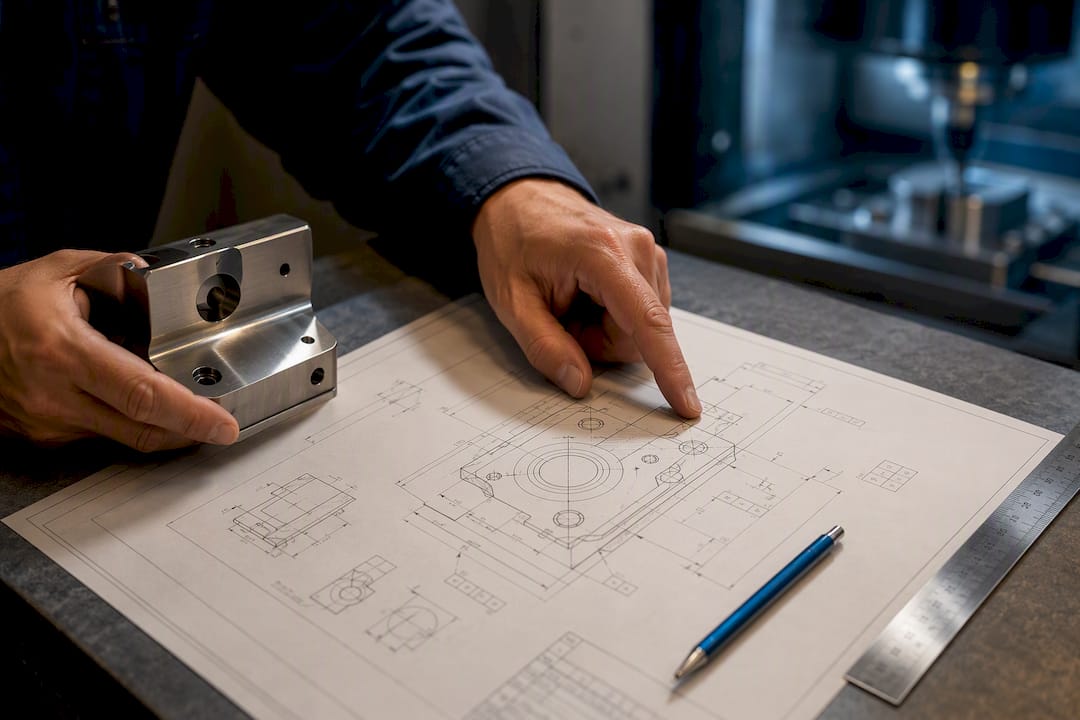
ASME Y14 is the primary engineering drawing standard used in the United States, and if you’re setting up a new drawing template or auditing an old one, start with two documents: ASME Y14.100 for drawing practices and title block requirements, and ASME Y14.5 for geometric dimensioning and tolerancing. ISO 8015 fills in for international contracts. Everything else in the Y14 family, including digital product definition rules and revision control conventions, builds upon those two foundations.
TL;DR:
- Most errors stem from unclear or missing datum references, inconsistent units, and unmarked projection angles, which cause build and inspection discrepancies.
- Digital models require explicit datums and complete PMI annotations to serve as authoritative definitions and prevent ambiguity during manufacturing and inspection.
- Following a strict revision and associated list process, along with clear title block standards, reduces mismatched parts and traceability issues across the supply chain.
- Different global standards like JIS and DIN have distinct conventions, especially regarding projection angles and tolerancing philosophies, so specifying the governing standard is crucial.
- Enforcing critical dimension flags and thorough checklist reviews before release can significantly lower scrap rates and improve first-article approval speed.
Table of Contents
- What Do the ASME Y14 Family and ISO Standards Actually Cover?
- What Does ASME Y14.100 Actually Require?
- How Do You Read a GD&T Feature Control Frame?
- What Belongs in Every Title Block, Sheet, and Line Style?
- When Should CAD Models Replace Traditional 2D Drawings?
- What Does a Shop-Floor-Tested Drafting Checklist Look Like?
- How Should You Manage Drawing Revisions and Associated Lists?
- How Do JIS, DIN, and Other Global Drawing Standards Compare?
- How Do Welding and Surface Texture Symbols Work on a Drawing?
- How Do You Apply Drawing Standards Across Aerospace, Automotive, and Multidisciplinary Projects?
- How Do You Verify Compliance With Drawing Standards?
- What Are the Most Common Drawing Errors, and How Do Standards Prevent Them?
- Where Can You Find the Official Standards and Reference Manuals?
- Standards in Practice: Reducing Scrap and Speeding Approval
- Sources
What Do the ASME Y14 Family and ISO Standards Actually Cover?
Most confusion about engineering drawing standards comes from treating ASME Y14 as one document instead of a family of them. It’s a coordinated set, and each part has a narrow job. Pull the wrong one and you’ll either miss a requirement or overspecify something nobody asked for.
Here’s how the parts break down for the ones you’ll touch most often:
- Y14.1 sets sheet sizes and format layout, covering both inch and metric formats.
- Y14.2 governs line conventions and lettering, the visual grammar of a drawing.
- Y14.3 covers multiview and sectional view projection.
- Y14.5 is geometric dimensioning and tolerancing, the rulebook for feature control frames and datums.
- Y14.24 defines the types of engineering drawings (detail, assembly, installation) and their minimum required content.
- Y14.34 covers associated lists, the parts lists and index documents that travel with an assembly drawing.
- Y14.35 governs revision practices, how you document and flag a change after release.
- Y14.41 covers digital product definition data practices, meaning model-based drawings and 3D annotation.
- Y14.100 is the umbrella standard tying the rest together and setting general drawing practices.
ASME’s Y14 series provides the core rules and templates that most CAD software and inspection tools are built around, and the parts are meant to be used together rather than in isolation. Y14.24 defines what kind of drawing you’re even making, and Y14.41 governs digital product definition once you’ve decided the model itself carries the authority.
ISO 8015 operates on a different principle worth understanding before you assume it’s a straight substitute for ASME. It establishes the “invocation principle,” meaning tolerancing rules only apply when a drawing explicitly references the standard. ASME Y14.5, by contrast, applies certain default rules automatically unless you state otherwise. That single difference changes how a drawing gets interpreted on two sides of an ocean, and it’s the reason a part that passes inspection under one system can get rejected under the other if nobody caught the mismatch.
For international work, the practical rule is this: if your customer’s contract cites ISO, invoke ISO 8015 explicitly on the drawing. If you’re supplying U.S. defense, aerospace, or industrial customers, Y14.100 and Y14.5 are almost always the expected baseline. When neither is specified in a purchase order, check your own company drawing standard first. Most manufacturing organizations, including Machiningtechllc, maintain an internal drafting standard that tailors ASME’s general rules into specific, checkable requirements for their own shop floor.
What Does ASME Y14.100 Actually Require?
Y14.100 doesn’t dimension anything itself. It’s administrative. It sets the ground rules for how a drawing gets structured, revised, and cross-referenced, and it tells you which other Y14 part to reach for depending on what kind of drawing you’re producing.
The scope is broader than most engineers assume on first read. Y14.100 establishes requirements for preparing and revising both manually drafted and computer-generated drawings, along with the associated lists that travel with them. It’s explicitly designed to be used alongside Y14.24 for drawing types and Y14.34 for parts lists, not as a standalone reference.
Tailoring is where Y14.100 gets genuinely useful for companies that don’t want to reinvent drafting policy from scratch. The standard allows nonmandatory appendices and company-specific tailoring notes, a structure that traces back to how the Department of Defense historically adapted ASME rules for its own procurement contracts. If your organization deviates from a default Y14.100 provision, that deviation should be recorded directly on the drawing or in the governing contract, not buried in an email chain nobody can find eighteen months later.
To mark a drawing as conforming, most drafting departments add a general note in or near the title block, something like: “This drawing is prepared in accordance with ASME Y14.100.” Some add the applicable Y14.5 revision year alongside it, since tolerancing conventions have shifted meaningfully across revisions.
Practically, Y14.100 drives a handful of decisions you’ll make on nearly every drawing:
- Default linear tolerances apply unless a feature control frame or general note overrides them.
- Title blocks need specific minimum fields: drawing number, revision, scale, material, and approval signatures at minimum.
- Cross-references to Y14.24 determine whether you’re producing a detail drawing, an assembly drawing, or something else with different content rules.
- Cross-references to Y14.34 apply the moment your drawing needs an associated parts list.
Skipping Y14.100 doesn’t just risk an audit finding. It means two engineers on the same team can build title blocks that look nothing alike, and a reviewer has no consistent baseline to check either one against.
How Do You Read a GD&T Feature Control Frame?
Geometric dimensioning and tolerancing exists because plus/minus dimensioning alone can’t describe how a real part needs to behave once it’s mated to another one. ASME Y14.5-2018 organizes tolerance types into five categories, and knowing which category applies to which problem is most of the battle.
Form controls (flatness, straightness, circularity, cylindricity) describe a feature’s shape independent of any other feature. Use flatness on a mounting face that needs to sit true against another surface. Orientation controls (perpendicularity, parallelism, angularity) relate a feature’s angle to a datum. Location controls (position, concentricity, symmetry) pin down where a feature sits relative to datums, and position is by far the most common callout on a production drawing. Profile controls a surface’s form, orientation, and sometimes location all at once, and it’s become the go-to tool for complex or free-form surfaces. Runout catches wobble in rotating parts, critical on shafts and anything spinning in a bearing.
Reading a feature control frame is a fixed sequence once you know the order: symbol, tolerance value, any modifiers, then datum references in priority order.
- Identify the symbol. A cylinder-in-a-box symbol means positional tolerance; a parallelogram means parallelism.
- Read the tolerance zone value. This is the total zone width the feature must fall within, often a diameter symbol followed by a number.
- Check for modifiers. An “M” in a circle means maximum material condition, which lets the tolerance grow as the feature departs from its worst-case size. An “L” means least material condition, the opposite logic.
- Read the datum references in order. The primary datum listed first constrains the most degrees of freedom, followed by secondary and tertiary datums that lock down what’s left.
- Confirm the datum features exist and are clearly flagged elsewhere on the drawing, usually with a boxed letter and a leader to the actual surface.
Miss a modifier or misread datum priority and the part can measure “in tolerance” on a CMM report while still failing to assemble on the line, which is the exact failure mode GD&T exists to prevent.
Statistic to know: ASME Y14.5-2018 added model views and shifted emphasis toward profile tolerancing specifically to support CAD-driven and model-based workflows, a structural change from earlier revisions built around paper drawings first. If your shop is fielding drawings that reference multiple Y14.5 revision years, the profile-heavy 2018 approach and the older, form-and-location-heavy conventions can read very differently for the same nominal feature.
What Belongs in Every Title Block, Sheet, and Line Style?
Skip the checklist mentality on this one and drawings start drifting apart within a department, let alone across suppliers. The elements below are the backbone every conforming drawing needs, drawn from ISO 7200 title block guidance and ASME’s sheet and lettering conventions.
- Title block fields. At minimum: drawing number, title, revision letter, scale, material and finish, drawn/checked/approved names and dates, and the applicable standard note (e.g., “per ASME Y14.100”).
- Sheet size and format. ASME Y14.1 defines standard sheet sizes for both inch (A through E) and metric (A4 through A0) formats, with format features like zone markings and revision blocks placed consistently regardless of size.
- Projection indicator. Third-angle projection dominates in the U.S. and is marked with its own standard symbol near the title block; first-angle projection is common in Europe and much of Asia. Never assume; always mark it.
- Line conventions. Object lines are thick and continuous, hidden lines are dashed, centerlines use a long-short-long pattern, and dimension/extension lines are thin. Mixing weights inconsistently is one of the fastest ways to make a drawing hard to read at a glance.
- Lettering height. Most standards recommend a minimum lettering height suitable for clear readability in general notes and dimension text on full-size prints, scaling up for reduced-size reproductions.
- Dimension spacing. Keep sufficient space between the first dimension line and the object outline, and between successive parallel dimension lines, enough room that arrowheads and text don’t collide during review or when a drawing gets marked up by hand.
Get these six right and most of what makes a drawing “look professional” on a customer’s first review just falls into place.
When Should CAD Models Replace Traditional 2D Drawings?
Digital product definition, governed by ASME Y14.41, lets a 3D CAD model carry the full authority for a part instead of a flat drawing. It works well for internally manufactured components where your CAM and CMM software can read model-based annotations directly, cutting translation errors between design intent and machine setup. It’s a harder sell for outside suppliers still working from printed drawings, or for legacy assemblies with decades of paper history behind them.
The catch, and it’s a real one: a bare CAD model without explicit datums and tolerances is not a complete definition. Model-based datasets that skip clear datum callouts and datum targets create exactly the kind of ambiguity Y14.41 was written to eliminate, not introduce, and it’s a documented failure mode in production environments relying on CAD as sole authority.
A minimum viable model-based dataset needs:
- Explicit datum features and datum targets, called out the same way they’d appear on a 2D drawing.
- Complete product manufacturing information (PMI), meaning tolerances, surface finish, and notes embedded as model annotations, not left implicit in the geometry.
- A defined export format (STEP AP242 is common) that preserves PMI when the file moves between CAD systems or into inspection software.
- A stated coordinate system tied to the physical datums, so CMM programming doesn’t have to guess at part orientation.
If your CAD-to-CMM workflow depends on model annotations surviving a file conversion intact, test that conversion before it becomes a production problem. A partner offering CAD and structural drawing services can be a useful sanity check when you’re standing up a model-based pipeline for the first time.
What Does a Shop-Floor-Tested Drafting Checklist Look Like?
Standards documents tell you what’s allowed. They don’t tell you what actually causes rework on a shop floor. After running high-volume Hydromat, CNC, and Wire EDM production for decades, certain drafting gaps show up over and over as the root cause behind scrapped first articles.
Run every drawing through this list before it leaves engineering:
- Units are stated once, clearly, and never mixed mid-drawing (inch and millimeter on the same print is a recurring source of scrap).
- Title block carries drawing number, revision, material, finish, and the governing standard note.
- Projection angle is marked, not assumed.
- Datums are flagged clearly and tied to functional mating surfaces, not arbitrary edges.
- Critical dimensions are visually distinguished, bolded, boxed, or flagged with a note, so operators and inspectors know which ones actually matter.
- Default tolerance block is present and matches your title block’s stated standard.
- Surface finish calls are specific (Ra values, not just “smooth finish”) and only appear where function requires them.
- Inspection callouts state acceptance criteria explicitly, not just a dimension with no context for how it’ll be measured.
Process matters here too. Hydromat-run parts often carry tight positional tolerances on multi-spindle rotary transfer features, so datum callouts need to reflect how the part actually indexes through the machine, not just how it looks in isolation. CNC milling and turning drawings should flag which dimensions are function-critical versus cosmetic, since over-tolerancing a non-critical feature adds inspection time for zero functional benefit. Wire EDM work frequently involves fine profile tolerances on internal features that traditional milling can’t reach, and those profile call-outs deserve the same scrutiny as any positional GD&T frame.
Pro Tip: Dimension to function, not to convenience. If a feature’s tolerance doesn’t trace back to a real fit, clearance, or performance requirement, loosen it. Tight tolerances on non-critical features are the single most common cause of unnecessary inspection time and rejected first articles.
For a deeper walkthrough of how these drafting rules connect to actual fabrication steps, Machiningtechllc’s engineer’s guide to component fabrication breaks down where drawing decisions ripple into machine setup.
How Should You Manage Drawing Revisions and Associated Lists?
A drawing without a disciplined revision history is a liability the moment two teams are working from what they assume is the same version. The revision block should capture, at minimum, the revision letter, the date of change, a brief description of what changed, and the approval signature or initials authorizing it.
Associated lists, governed under Y14.34, matter most on assembly drawings where a parts list or index needs to stay synchronized with the drawing itself. Every part number referenced on an assembly print should trace directly to a line item on its associated list, with matching revision levels. A mismatch here is one of the most common sources of the wrong part showing up on a build.
For electronic revision control, a few habits keep traceability intact:
- Use consistent file naming that encodes drawing number and revision level, never a generic “final_v2” naming scheme.
- Store superseded revisions in an accessible archive rather than overwriting them, since audits and warranty claims often need to reference an older configuration.
- Tag metadata (author, approval date, CAD software version) directly in the file properties, not just in a separate log that can drift out of sync.
- Require a documented reason for every revision, even minor ones, so a reviewer six months later understands why a dimension moved.
How Do JIS, DIN, and Other Global Drawing Standards Compare?
ASME Y14 and ISO 8015 dominate North American and much of international manufacturing, but they’re not universal. Japan’s JIS (Japanese Industrial Standards) and Germany’s DIN (Deutsches Institut für Normung) govern significant portions of Asian and European supply chains, and both share more structural DNA with ISO than with ASME.
JIS drawing conventions generally follow first-angle projection by default, in contrast to ASME’s third-angle default, which means a drawing produced for a Japanese customer without an explicit projection callout can be misread entirely if a U.S. drafter assumes their own convention. JIS also tends to follow ISO’s tolerancing philosophy more closely than ASME’s, including the invocation principle.
DIN standards, particularly DIN 406 for dimensioning, share substantial overlap with ISO 128 and ISO 8015 since Germany was heavily involved in shaping those international standards in the first place. European suppliers working under DIN will often default to first-angle projection as well, and their surface finish and tolerance symbols track closely with ISO conventions rather than ASME’s.
The practical takeaway for anyone managing a multinational supply chain: never assume projection angle, tolerancing philosophy, or symbol meaning carries over between customers in different regions. A drawing note stating the governing standard, ASME Y14.100, ISO 8015, JIS B 0001, or DIN 406, removes the guesswork before a part ever reaches a machine.
How Do Welding and Surface Texture Symbols Work on a Drawing?
Symbol standards exist so a drawing communicates identically to every reader, regardless of language. Two symbol families cause the most confusion in practice: welding symbols and surface texture symbols.
Welding symbols follow AWS A2.4 in the U.S. (closely coordinated with ASME conventions), built around a horizontal reference line with a symbol below it indicating the weld type on the near side and above it for the far side. A fillet weld symbol is a right triangle; a groove weld uses shapes that vary by joint prep. Tail notations add supplemental instructions like weld process or specification reference. Get the near-side/far-side placement wrong and a welder lays down a bead on the wrong face of the joint entirely.
Surface texture symbols, governed under ASME Y14.36, use a checkmark-like symbol with a roughness average (Ra) value placed above the horizontal line. Additional marks indicate whether material removal is required, prohibited, or optional. A bare checkmark with no value is technically incomplete and shouldn’t pass drawing review; the number is what actually tells a machinist how fine a finish to hold.
Both symbol families reward consistency far more than complexity. A drawing with three different informal ways of calling out the same fillet weld is harder to execute correctly than one using a single symbol precisely per standard.
How Do You Apply Drawing Standards Across Aerospace, Automotive, and Multidisciplinary Projects?
Standards don’t change industry to industry, but the rigor with which they’re enforced does. Aerospace and defense work typically layers additional requirements on top of ASME Y14, things like AS9100 quality management provisions and customer-specific first-article inspection formats, meaning the drawing itself may need extra callouts beyond baseline Y14.100 requirements.
Automotive drawings frequently follow IATF 16949 quality frameworks alongside ASME or ISO dimensioning, with heavier emphasis on process capability data tied back to specific tolerance callouts. A tolerance on an automotive drawing often isn’t just a spec; it’s a target that production process capability studies need to demonstrate the process can actually hold.
Multidisciplinary projects, where mechanical, electrical, and software teams all touch the same assembly, create their own risk: a mechanical drawing’s datum structure needs to align with how electrical harness routing or software-controlled actuator positioning references the same physical part. The fix isn’t a different standard; it’s making sure every discipline references the same datum scheme from the same drawing, rather than each team improvising its own coordinate assumptions.
The consistent thread across every industry context is that ASME Y14.100 and Y14.5 remain the baseline. Industry-specific frameworks add verification and documentation requirements on top, but they rarely replace the core dimensioning and drafting conventions underneath.
How Do You Verify Compliance With Drawing Standards?
Quality assurance on a drawing itself, not just the part it describes, deserves its own review step, and most organizations skip it. A drawing can be dimensionally perfect and still violate the very standard it claims to follow if the title block is missing a required field or the projection angle isn’t marked.
A workable compliance review checks three things independently: administrative completeness (title block fields, revision block, governing standard note), technical correctness (datum logic, tolerance stack-up, GD&T symbol usage), and cross-reference integrity (does the associated parts list match the assembly drawing, do sheet references point to sheets that exist). Assign a second reviewer, ideally someone who didn’t draft the original, since the person who created a drawing rarely spots their own datum logic errors.
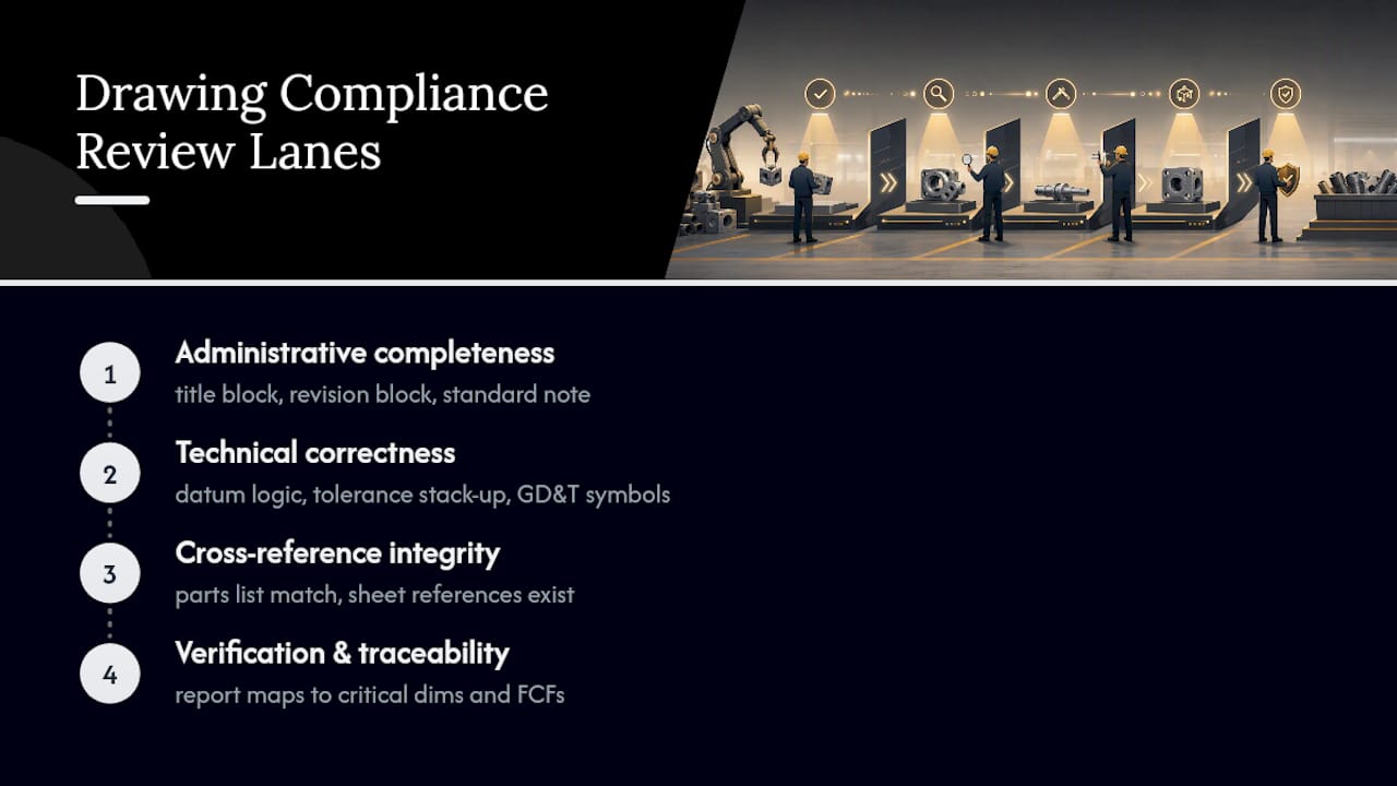
First-article inspection reports should map directly back to the drawing’s critical dimensions and feature control frames, not to a generic dimensional checklist. If an inspection report can’t be traced line by line to a specific callout on the drawing, the drawing and the inspection process have drifted apart, and that gap is exactly where scrap and disputed rejections come from.
What Are the Most Common Drawing Errors, and How Do Standards Prevent Them?
A handful of errors account for most rework tied back to the drawing itself rather than the manufacturing process. Missing or ambiguous datum references top the list. Without a clearly flagged primary datum, an inspector and a machinist can each pick a different reference surface and both be technically defensible, which is precisely the ambiguity Y14.5’s datum reference frame rules exist to eliminate.
Inconsistent units run a close second, usually surfacing when a legacy drawing gets partially updated and someone adds a millimeter dimension to an inch-based print without converting or flagging it clearly. Over-tolerancing shows up constantly on non-critical features, adding inspection burden for zero functional benefit and often driving up part cost for no real gain in fit or function.
Missing projection angle callouts cause parts to be built mirrored or rotated incorrectly, especially on drawings that cross between ASME and JIS or DIN conventions without anyone flagging the difference. And incomplete revision histories, a changed dimension with no documented reason or approval, create disputes months later when nobody can explain why a part changed and whether the change was ever properly authorized.
Every one of these errors traces back to a specific standard provision built to prevent it. The standards aren’t bureaucratic overhead; they’re a running list of mistakes the industry has already made and decided not to repeat.
Where Can You Find the Official Standards and Reference Manuals?
The primary standards themselves are purchased documents, but a few practical references are freely available and worth bookmarking:
- ASME Y14 standards catalog lists every part in the family, including Y14.24 and Y14.41, with purchase links for the current editions.
- NASA GSFC’s Engineering Drawing Standards Manual is a free PDF showing how one major organization tailored ASME’s general rules into concrete, checkable drafting conventions, including spacing and title block examples.
- ISO 8015 and ISO 128 cover tolerancing invocation principles and general drawing conventions internationally; summaries are available through ISO’s own catalog, though full texts require purchase.
Standards in Practice: Reducing Scrap and Speeding Approval
The gap between knowing a standard and enforcing it consistently is where most manufacturing rework actually lives. Engineers who can recite Y14.5 datum rules still routinely send drawings to the floor with ambiguous primary datums or missing surface finish values, and the standard itself never catches that at the design desk. Enforcement has to happen through a checklist, not memory.
The most measurable improvement in first-article yield I’ve seen tied to drafting practice comes from a single change: requiring every critical dimension to carry a visible flag, bold text, a boxed callout, anything that separates it from cosmetic dimensions, before a drawing leaves engineering review. It sounds almost too simple to matter, but it forces the person releasing a drawing to actually decide which features are functionally critical, rather than leaving that judgment call to whoever picks up the print on the machine floor. That decision, made once at the desk instead of repeatedly at the machine, is where scrap actually gets prevented.
Some manufacturing firms maintain internal drafting templates tailored from ASME Y14.100 and Y14.5 into checkable rules for high-volume Hydromat, CNC, and Wire EDM production. If your team is standardizing drawing practices across a supply chain or just trying to cut first-article rejection rates, our engineering and manufacturing services team reviews drawing packages as part of onboarding new part programs, and it’s usually where the biggest, fastest gains show up.
— Andrew
Sources
- ASME Y14 | Y14 Standards — ASME
- ASME Y14.5 – Dimensioning and Tolerancing (ASME PDF)
- ENGINEERING DRAWING STANDARDS MANUAL – S3VI (NASA GSFC)