

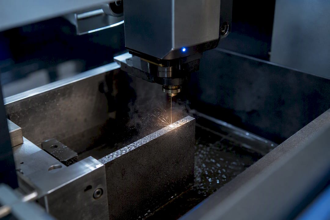
Electrical discharge machining reliably produces surfaces from roughly Ra 3.2 µm on aggressive roughing cuts down to Ra 0.1 to 0.2 µm with slow, low-energy finishing passes, and specialty setups can push finer still. Pulse-on time and peak current are the two levers that matter most: dial both down and you get a smoother surface, but you also give up material removal rate and often add a recast layer that demands its own attention.
TL;DR:
- Lowering both pulse-on time and peak current reduces surface roughness but significantly decreases material removal rate and may increase recast layer thickness.
- Recast layers and heat-affected zones, which vary with discharge energy, critically impact fatigue life and fatigue-critical component performance.
- Specifying surface finish solely by Ra is insufficient; area-based parameters like Sa and Sz provide a more comprehensive understanding of surface quality and functional performance.
- Fine surface finishes from multiple skim passes are time-intensive, and their economic benefits depend on the specific functional requirements and geometry constraints.
- Controlling thermal parameters and understanding material behavior are essential to optimize surface finish and minimize thermal damage across different alloys and section thicknesses.
Table of Contents
- What Controls Surface Roughness in EDM Machining
- Multi-Pass Strategy: Roughing, Trim, and Finish Passes
- Why Recast Layer and Heat-Affected Zone Matter More Than Ra
- How to Specify EDM Surface Finish on Drawings and RFQs
- Post-EDM Finishing: Grinding, Etching, and Remelt Options
- What Shops Should Prove Before You Trust Their EDM Finish
- Does EDM Finish Affect Wear Resistance and Friction, Not Just Fatigue?
- How Does EDM Surface Finish Compare to Milling, Grinding, and Turning?
- Which Industries Depend on Precise EDM Surface Finish?
- Optimizing EDM Parameters by Material and Section Thickness
- Editorial Take: EDM Finish Is a Surface Engineering Problem
- Get Reliable EDM Surface Finish Without Managing the Process Yourself
- Sources
What Controls Surface Roughness in EDM Machining
Every spark in the gap melts and vaporizes a tiny crater of material, and the size of that crater is what surface roughness actually measures. Bigger discharges make bigger craters. Smaller discharges make a shallower, more uniform texture. That single relationship is the whole story behind EDM surface finish, and it’s why the same machine can cut a part with a jagged Ra of 6 µm one day and a mirror-like Ra of 0.15 µm the next, using nothing but different generator settings.
Two parameters dominate that crater size. Pulse-on time (Ton) sets how long each discharge dumps energy into the workpiece, and peak current (Ip) sets how much energy flows during that pulse. Push either one up and you widen and deepen the crater, which raises Ra. Pull them down and the craters shrink. Statistical process studies on wire EDM confirm these two inputs are the most significant drivers of surface roughness, ahead of nearly everything else on the control panel.
A handful of supporting parameters shape the finish around the edges:
- Pulse-off time affects flushing and gap stability more than roughness directly, but poor flushing lets debris re-strike the surface and roughen it.
- Pulse frequency interacts with Ton to determine total heat input per unit time.
- Servo feed settings control gap consistency, which affects how evenly discharges distribute across the surface.
- Dielectric flow and wire tension (for wire EDM) reduce stray arcing that otherwise leaves random deep pits.
- Electrode or wire material changes spark energy distribution and, on wire machines, wire diameter and coating change achievable finish ceilings.
Statistic to know: In ANOVA-based studies of stainless steel wire EDM, pulse-on time and current intensity rank as the two statistically significant factors governing surface roughness, with a measurable trade-off against material removal rate baked into every parameter change.
Cutting Ra in half by dropping Ton and Ip typically cuts removal rate by more than half. That asymmetry is the entire economics of EDM finishing.
Multi-Pass Strategy: Roughing, Trim, and Finish Passes
Shops don’t chase a fine finish in one pass. They rough hard, then walk the energy down through a series of trim and finish passes until the surface hits spec.
- Roughing pass — high Ton and Ip to clear bulk material fast; Ra typically lands between 3 and 6 µm, and recast layer is thickest here.
- Semi-finish pass (skim 1) — reduced current, offset just beyond the roughing kerf, knocking Ra down to roughly 1 to 2 µm.
- Finish pass (skim 2 or 3) — low-energy, short Ton, tight servo control; final Ra can reach 0.2 to 0.4 µm on most steels.
- Micro-finish pass (optional) — sub-microsecond pulses via RC-type or low-capacitance circuits, reserved for parts needing Ra below 0.1 µm.
Every added skim pass buys finish at the cost of cycle time, so shops budget extra hours only when the drawing actually calls for it. RC-type generators and stochastic electrode orbiting techniques have been shown to push wire EDM finishes into sub-0.06 µm Ra territory in controlled lab conditions, though that hardware is specialized rather than standard-issue.
On wire machines, coated and diamond wires reduce wire wear and let feed rate stay more consistent through a finish pass, which shows up directly as tighter surface uniformity.
Pro Tip: Don’t spec the finest achievable Ra by default. Every skim pass past the second one adds disproportionate cycle time for diminishing surface gain — match the pass count to the functional requirement, not to what the machine is theoretically capable of.
Deciding between on-machine finishing and shipping parts out for secondary treatment usually comes down to geometry: deep slots and small radii favor staying on the EDM, while open faces are often cheaper to finish off-line.
Why Recast Layer and Heat-Affected Zone Matter More Than Ra
A part can measure a beautiful Ra and still fail in service, because Ra only describes the surface topography. It says nothing about what happened underneath it.
Every EDM discharge melts a thin skin of material that resolidifies without ever being removed. This is the recast layer (sometimes called the white layer), and it sits on top of a heat-affected zone (HAZ) where the base metal’s grain structure and hardness have been altered by rapid thermal cycling. EDM’s electrothermal mechanism inherently produces this recast, spatter, and HAZ, and it forms whether the operator wants it or not.
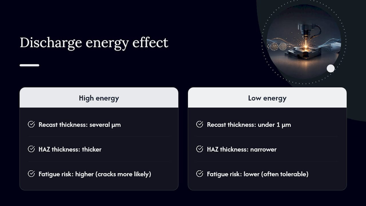
Recast thickness varies with discharge energy: aggressive roughing passes can leave layers of several microns, while low-energy finishing passes can bring that down to under a micron. Thin recast under roughly 1 µm is often tolerable, but thicker or cracked recast is a different problem entirely. The layer commonly carries carbon and other contaminants transferred from the electrode and dielectric fluid, and it sits in a state of tensile residual stress rather than the compressive stress that protects against fatigue cracking.
Statistic to know: Fatigue-focused reviews of EDM surfaces treat recast and HAZ, not surface roughness, as the leading cause of reduced fatigue life in EDM-finished parts — a distinction that matters enormously for anything cyclically loaded.
Material behavior varies here too. Hardened tool steels and stainless alloys tend to form harder, more brittle recast that’s prone to microcracking. Superalloys and carbides often need narrower parameter windows to avoid excessive thermal damage, since their poor thermal conductivity concentrates heat right at the surface. When integrity matters, engineers pick one of three paths: remove the layer (grinding, micro-blasting, chemical etch), alter its properties after the fact (heat treatment to relieve residual stress), or replace it entirely through remelt techniques like electron-beam irradiation, laser remelt, or powder-mixed EDM.
How to Specify EDM Surface Finish on Drawings and RFQs
Ra alone tells an incomplete story, and specifying it as the sole acceptance criterion is one of the most common mistakes on EDM drawings. Ra averages peaks and valleys along a single line profile. It can’t tell you whether a surface is uniformly textured or scattered with a few deep gouges that will concentrate stress or trap contaminants.
Comparative studies of 2D versus 3D surface parameters recommend area-based (Sa) and functional parameters for EDM surfaces specifically because they capture what Ra misses:
- Sa — average roughness over an area rather than a line; generally reads higher than Ra on the same surface.
- Sz — maximum peak-to-valley height across the sampled area, useful for catching outlier defects.
- Rsk (skewness) — reveals whether the texture is dominated by peaks or valleys, relevant to wear and sealing performance.
- Rku (kurtosis) — describes how sharply peaked the height distribution is.
- Rmr (material ratio) — the bearing-area curve, valuable for predicting contact and wear behavior.
Research comparing 2D and 3D metrics on EDM surfaces has found Sa-to-Ra and Sz-to-Rz ratios vary enough between parts that specifying an area instrument, not just a profilometer, is worth the added cost when function is on the line.
| Shop finish grade | Approximate Ra range | Typical use case |
|---|---|---|
| Rough EDM (roughing pass) | 3 to 6 µm | Bulk removal, non-critical bores |
| Medium finish (semi-finish skim) | 1 to 2 µm | General tooling surfaces |
| Fine finish (finish skim) | 0.2 to 0.4 µm | Sealing surfaces, mating faces |
| Micro finish (low-energy/RC pulse) | Below 0.1 µm | Optical tooling, medical components |
A thorough surface finish specification includes the surface parameter (e.g. Ra or Sa), sampling area, measurement instrument class, and tolerance limits rather than only stating a single Ra value. The ASME-backed surface finish chart is a useful reference when translating shop-floor finish grades into the Ra or Sa values a drawing needs to state explicitly.
Post-EDM Finishing: Grinding, Etching, and Remelt Options
Once a part comes off the EDM, the question becomes whether the finish and the subsurface layer beneath it are good enough as they stand, or whether something needs to happen next.
Mechanical removal covers grinding and abrasive micro-blasting. Both strip recast effectively and are the default choice on accessible flat or cylindrical surfaces, but they’re limited on complex internal geometry that a grinding wheel or blast nozzle can’t reach.
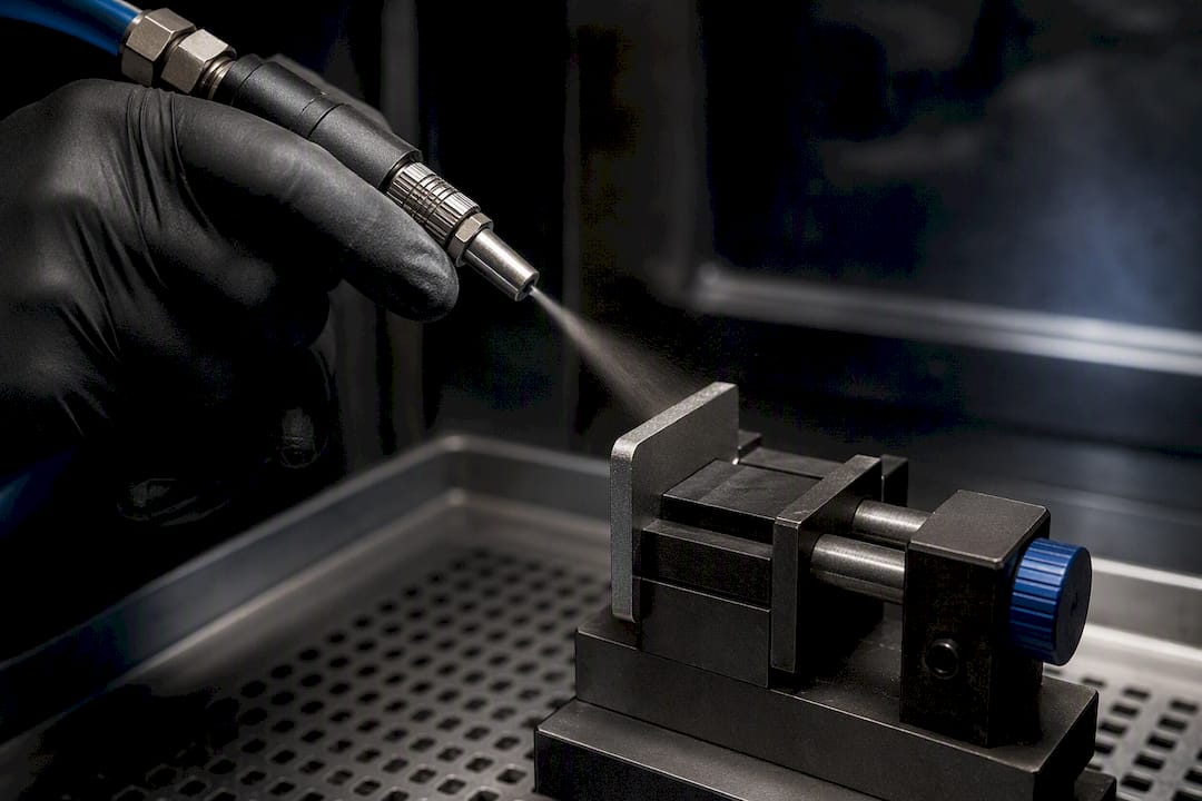
Chemical and electrochemical methods — etching and electrochemical polishing — remove material uniformly without mechanical contact, which makes them well suited to delicate features, thin walls, or internal passages where grinding risks distortion.
Advanced remelt and coating techniques, including pulsed electron-beam irradiation, laser remelt, and powder-mixed EDM, go further than simple removal. Powder-mixed EDM and related surface-engineering variants can intentionally alter surface chemistry rather than just cleaning it up, which is worth considering when the goal is a functional coating rather than a return to base metal.
- If the drawing calls out fatigue or corrosion resistance, plan on full recast removal, not just smoothing.
- If the surface only needs to look clean and measure a target Ra, a light micro-blast or etch is usually enough.
- If tolerance is tight, budget for the material the removal step itself takes off; grinding a recast layer away still consumes dimension.
Pro Tip: Ask for a cross-section before assuming a surface is clean. Visual inspection alone may not detect cracked recast layers, which often require cross-section microscopy for reliable identification.
What Shops Should Prove Before You Trust Their EDM Finish
Since 1985, Machiningtechllc has run wire EDM alongside CNC milling and turning inside a 70,000-square-foot facility built for high-volume, tight-tolerance work. That kind of infrastructure matters here because consistent EDM surface finish isn’t a one-time achievement. It’s a repeatability problem across thousands of parts.
A capable shop should be able to show, not just claim, its process control:
- Surface metrology on hand for both profile (Ra) and areal (Sa, Sz) measurement, not just a stylus profilometer.
- Cross-section capability to verify recast thickness on fatigue- or corrosion-critical parts.
- Documented process windows for pass sequencing rather than one-off parameter tweaking per job.
- Reference to a recognized standard, such as an ASME-backed surface finish chart, when translating drawing callouts into machine settings.
Before you hand off an EDM-finish-sensitive part, ask a prospective supplier directly: can they measure Sa and Rsk, not just Ra? Do they have experience with your specific alloy’s recast behavior? Can they walk you through their roughing-to-finish pass sequence and explain where recast removal fits in? A shop that answers those questions in specifics, rather than generalities, is the one worth trusting with parts that have to survive cyclic loading or a corrosive environment.
Does EDM Finish Affect Wear Resistance and Friction, Not Just Fatigue?
Yes, and it’s an area that gets far less attention than fatigue or corrosion. The recast layer’s altered hardness changes how a surface responds to sliding contact, and that shows up in wear resistance and friction behavior long before any crack initiates.
Recast material is often harder and more brittle than the parent metal beneath it, since it forms from rapidly quenched molten material rather than the alloy’s normal grain structure. On some parts that brittle skin flakes under repeated sliding contact, generating wear debris that accelerates damage to both mating surfaces. On others, particularly where the recast is thin and adherent, the harder outer skin actually improves initial wear resistance until it eventually breaks through to softer material underneath.
Friction coefficient tracks surface texture in a way that’s easy to overlook when specifying finish. A high-Rsk surface dominated by sharp peaks generates more initial friction and wears those peaks down quickly in a break-in period, while a surface with a more even height distribution (lower kurtosis) tends to hold a steadier friction coefficient over time. That’s part of why the material-ratio parameter (Rmr) matters for bearing surfaces and sliding fits: it predicts how much real contact area exists at a given wear depth, which is a much better proxy for running-in behavior than Ra alone.
For mold and die surfaces, this plays out directly in part-release friction, and for hydraulic or pneumatic components it plays out in seal wear rates. Neither shows up on a basic Ra callout.
How Does EDM Surface Finish Compare to Milling, Grinding, and Turning?
Every subtractive process leaves its own signature, and EDM’s signature is fundamentally different because it’s thermal, not mechanical. Milling and turning leave directional tool marks with a texture that follows feed rate and tool nose radius; the resulting surface tends to be anisotropic, smoother in one direction than another. Grinding produces a similarly directional pattern but at much finer scale, often reaching Ra values below what EDM achieves without extensive finish passes.
EDM’s texture is isotropic. Because material removal happens through discrete sparks rather than a cutting edge dragging across the surface, the crater pattern looks statistically similar in every direction. That isotropy is genuinely useful for parts where directional friction or sealing behavior would be a problem, but it comes with the recast layer that mechanical processes don’t produce at all. A ground or turned surface has residual stress patterns from cutting forces, not from localized melting, and generally doesn’t carry the same fatigue penalty at equivalent Ra.
Where EDM wins outright is geometry mechanical processes can’t touch: deep slots, sharp internal corners, hardened materials that would destroy a cutting tool, and complex 3D cavities in mold and die work. Where mechanical processes win is finish-per-dollar on open, accessible geometry, since grinding a flat face to a fine Ra is faster and cheaper than skimming it through multiple EDM finish passes. The honest comparison isn’t which process gives a better finish. It’s which process fits the geometry and material, with finish quality as a downstream consequence of that choice.
Which Industries Depend on Precise EDM Surface Finish?
Aerospace and defense components lean on EDM specifically because tight-tolerance geometry in high-strength alloys often can’t be cut any other way, and fatigue-critical parts in that world make recast control non-negotiable rather than optional. A turbine blade cooling hole or a structural fitting with a cracked recast layer isn’t a cosmetic problem. It’s a crack initiation site waiting for a load cycle.
Mold and die manufacturing cares about a different axis entirely: surface texture governs how plastic or metal releases from a cavity, so finish specification there is about friction and cosmetic transfer onto the molded part, not fatigue. Medical device components split the difference, often needing both a fine, contamination-free surface for biocompatibility and tight geometric control for small, complex features.
Firearm component manufacturing sits closer to the aerospace end of that spectrum: tight tolerances, hardened materials, and functional surfaces on parts that see repeated mechanical cycling over their service life. Industrial tooling and die-cast components, by contrast, often tolerate coarser EDM finishes because the functional requirement is dimensional accuracy on a hardened die face, not a mirror surface.
The through-line across every one of these industries is that the finish specification should follow from the part’s actual failure mode, not from a default Ra number pulled off a generic chart.
Optimizing EDM Parameters by Material and Section Thickness
Material choice changes the entire parameter conversation, because thermal conductivity, melting point, and electrical resistivity all shape how a given pulse energy translates into crater size and recast thickness.
Tool steels and general stainless alloys machine predictably across a wide parameter range, which is why most published parameter guidance centers on them. Superalloys like Inconel, with their poor thermal conductivity, concentrate heat right at the discharge site; that means the same Ton and Ip that produce a moderate finish on stainless steel can drive deeper thermal damage on a nickel superalloy, so finish passes there often need lower energy settings than the material’s hardness alone would suggest. Carbide and other sintered materials bring their own quirk: binder phases and carbide grains erode at different rates, which can leave a rougher, more heterogeneous surface at the same nominal Ra as a homogeneous steel.
Section thickness matters just as much as alloy. Thin sections and delicate features need reduced energy not just for finish quality but to avoid thermal distortion and stress-relief warping after machining. Thick sections tolerate more aggressive roughing passes since there’s more surrounding material to act as a heat sink, but they typically need proportionally more finish passes to bring a larger surface area down to spec. Modern machine platforms with adaptive servo control and stable fixturing, the kind found on large-format 5-axis machining centers, help hold consistent gap conditions across varying section thickness within a single part, which keeps finish uniform where older equipment would show visible transitions between thick and thin regions.
Editorial Take: EDM Finish Is a Surface Engineering Problem
Most EDM guidance treats surface finish as a number to hit: dial in a Ra target, adjust Ton and Ip until the profilometer agrees, and call the job done. That framing misses what actually determines whether a part survives its service life.
EDM doesn’t just remove material. It thermally transforms whatever surface it touches, and that transformation runs deeper than the roughness reading shows. The conventional advice under-weights recast and HAZ because they’re harder to measure than Ra and easier to ignore until a part fails in the field. A shop chasing a fine Ra with aggressive finish passes can hand over a part that looks better and performs worse than a coarser one with a thinner, cleaner subsurface layer.
If there’s one thing worth prioritizing first, it’s asking what the part’s failure mode actually is before specifying a finish at all. A sealing face cares about Sa and material ratio. A fatigue-loaded bracket cares about recast thickness and residual stress far more than roughness. Treat EDM as surface engineering, where the finish and the metallurgy underneath it are one decision, not two, and the parameter and pass-sequencing choices in this guide start making a lot more sense.
— Andrew
Get Reliable EDM Surface Finish Without Managing the Process Yourself
Our facility runs wire EDM alongside CNC milling and turning, allowing finish specifications, recast control, and dimensional tolerances to be managed cohesively without involving multiple subcontractors. That matters most for OEMs and manufacturers who need parts that hit a documented Ra or Sa target and pass a fatigue-critical inspection on the first run, not the third.

If your drawings call for tight-tolerance geometry in hardened steels, stainless alloys, or firearm-grade materials, wire EDM machining from Machiningtechllc covers everything from prototype quantities through full production. Engineers who need to understand the underlying process before writing an RFQ can start with the EDM technology primer, then move straight to a quote once the finish and integrity requirements are locked down. For OEMs weighing contract machining against building out in-house capacity, Machiningtechllc’s contract machining services are built for exactly the kind of high-volume, tight-tolerance production this guide has been describing. Send over your part specs and finish requirements, and get a straight answer on what it takes to produce them at scale.
Sources
- PMCID article (process-parameter influence on EDM surface roughness)
- The EDM surface: Topography, chemistry, and metallurgy (technical review / thesis)
- Study: Influence of process parameters on wire-EDM for stainless steel (Material journal, 2023)