


TL;DR:
- A disciplined step-by-step prototyping process reduces product failure rates and controls development costs. It involves sequential stages from ideation to testing, with each focus tailored to the project’s needs and risk level. Multiple iteration cycles refine the design efficiently, emphasizing early validation and careful documentation.
The step by step prototyping process is a sequential, iterative method that transforms a product concept into a validated physical or digital artifact through defined stages of design, build, test, and refinement. Nearly 50% of product designs arrive late or never reach market, and about 30% fail after release. Those numbers reflect what happens when teams skip structured prototyping or treat it as optional. A disciplined prototyping workflow is the single most reliable way to catch design errors before they become production costs.
What are the core steps in a standardized prototyping process?
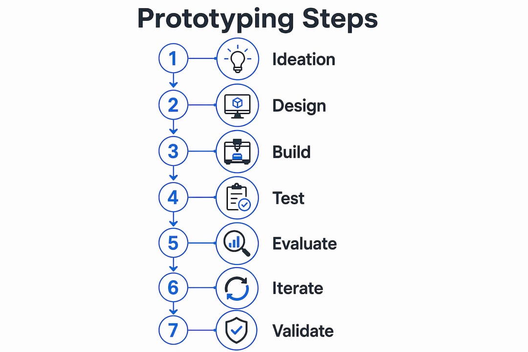
The seven-step industrial prototyping framework is the recognized industry standard for moving from concept to production-ready design. Each step has a defined output, and skipping any one of them typically forces a costly backtrack later. The seven steps are:
- Ideation and research — Define the problem, gather user requirements, and identify constraints. Output: a written problem statement and feature list.
- Conceptual drawing — Sketch rough concepts by hand or in basic digital tools. Output: annotated concept sketches showing form and function.
- CAD modeling — Build a three-dimensional digital model using CAD software. Output: a dimensioned model ready for simulation or toolpath generation.
- Support planning — Identify manufacturing method, materials, tolerances, and fixturing needs. Output: a build plan with material specs and process notes.
- Proof of concept — Build a rough, low-cost version to test the core function only. Output: a working demonstration of the primary mechanism.
- Physical prototype development — Produce a higher-fidelity prototype using the target manufacturing process, such as CNC milling, 3D printing, or wire EDM. Output: a testable artifact that closely represents the final part.
- Testing and iteration — Run structured tests, collect data, and refine the design. Output: a validated design or a documented list of changes for the next cycle.
The table below summarizes each stage, its primary focus, and a realistic time window for a mechanical component prototype.
| Stage | Primary focus | Typical duration |
|---|---|---|
| Ideation and research | Problem definition, requirements | 1–3 days |
| Conceptual drawing | Form exploration, rough concepts | 1–2 days |
| CAD modeling | Dimensional accuracy, fit | 2–5 days |
| Support planning | Process selection, material spec | 1–2 days |
| Proof of concept | Core function validation | 3–7 days |
| Physical prototype | Fidelity, manufacturability | 5–14 days |
| Testing and iteration | Performance, user validation | 3–10 days per cycle |
Pro Tip: Document the output of each stage in a shared project log. Engineers who skip documentation routinely repeat work in later cycles because no one can reconstruct the reasoning behind earlier decisions.
How do you plan and prepare for prototyping effectively?
Effective preparation starts with defining a single testable question for each prototype build. Vague goals produce vague results. Before touching any tool, write down exactly what the prototype must prove or disprove.
Fidelity selection is the most consequential planning decision you will make. Low-fidelity prototypes are best early in the process to validate flow, navigation, and basic geometry. High-fidelity prototypes belong at the end of the design cycle, just before production handoff, when you need to confirm fit, finish, and interaction quality. Building a high-fidelity prototype in week one wastes time and money on details that will change.
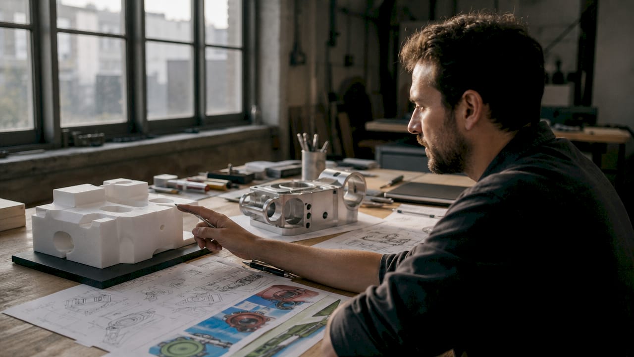
Matching your tools to the fidelity level and use case prevents over-engineering at the wrong stage. The table below maps common prototyping tools to fidelity level and appropriate use case.
| Tool | Fidelity level | Best use case |
|---|---|---|
| Hand sketches | Low | Concept exploration, team alignment |
| CAD software (e.g., SolidWorks, Fusion 360) | Medium to high | Dimensional modeling, tolerance planning |
| FDM 3D printing | Low to medium | Form and fit checks, proof of concept |
| CNC milling or turning | High | Functional mechanical prototypes |
| Wire EDM | High | Complex geometry, tight-tolerance parts |
| Wireframing tools (e.g., Figma) | Low to medium | UI and workflow validation |
Key preparation steps before the first build:
- Write a one-sentence hypothesis: “This prototype will prove that [mechanism X] can achieve [performance target Y].”
- List the three riskiest assumptions in the design and confirm the prototype addresses at least one of them.
- Set a hard time limit for the build phase to prevent scope creep.
- Identify the test participants or test conditions before building, not after.
- Confirm material availability and lead times for any machined components.
Pro Tip: The most effective prototypes target the single riskiest assumption with tight constraints. A short build window forces focus and prevents teams from adding features that belong in a later cycle.
What are the detailed execution phases of building, testing, and iterating?
The execution phase is where most prototyping workflows break down. Teams either overbuild before testing or test too loosely to generate useful data. A disciplined build-test-iterate cycle fixes both problems.
The iterative prototyping loop is defined as build, test, revise, and repeat until design questions are resolved. Experts recommend 3–5 testing cycles per feature, which reduces design error costs by 30% through early detection. That cost reduction compounds across a full product development program.
Follow these five execution steps for each iteration cycle:
- Build the minimum viable prototype. Include only the components needed to test the specific hypothesis. Every extra feature adds build time and introduces variables that obscure test results.
- Test with 5–8 representative users or test conditions. For mechanical components, this means running the part through its intended load, temperature, or tolerance conditions. For product interfaces, use task-based scenarios with real users.
- Observe silently. Do not guide, explain, or prompt during testing. User hesitation and friction points provide more valid feedback than any answer to a direct question.
- Analyze findings by severity. Categorize issues as critical (blocks function), moderate (degrades performance), or minor (cosmetic). Address critical issues before moving to the next cycle.
- Iterate narrowly. Change only what the test data tells you to change. Broad redesigns between cycles make it impossible to isolate which change produced the improvement.
AI-assisted prototyping workflows can compress build cycles significantly by maximizing time on problem framing and minimizing time on setup. For software or digital prototypes, this means spending the first 15 minutes defining the problem precisely before writing a single line of code or placing a single component.
User testing best practices for physical and digital prototypes:
- Recruit test participants who match the actual end user profile, not colleagues.
- Run tests in the environment where the product will actually be used.
- Record sessions when possible to catch details missed during live observation.
- Debrief immediately after each session while observations are fresh.
- Share findings with the full design team before starting the next build cycle.
Pro Tip: For precision machined prototypes, always test at the tolerance boundary, not just at nominal dimensions. Parts that pass at nominal frequently fail at the edge of the tolerance band, and that failure mode only shows up under real operating conditions.
What common pitfalls hurt prototyping success rates?
Overbuilding is the most common and most expensive prototyping mistake. Engineers add features, finishes, and tolerances that the current test does not require. The result is a prototype that took three times as long to build and still does not answer the core design question.
The rebuild trap is a close second. Over-guided tests invalidate feedback, and rebuilding prototype components from scratch wastes resources that could go toward another iteration cycle. Choose workflows and tools that allow you to reuse prototype components in the final production design wherever possible.
Common pitfalls to avoid:
- Fidelity mismatch. Using a high-fidelity prototype to test a concept that only needs a sketch wastes a week of build time.
- Over-guiding users. Explaining how the product works before a test contaminates the results. Let the design speak for itself.
- Skipping the proof-of-concept stage. Teams that jump from CAD to full physical prototype skip the cheapest opportunity to catch fundamental design flaws.
- Too few iteration cycles. One or two rounds rarely resolve all critical issues. Plan for at least three cycles per major feature.
- Premature pivot. Changing the core concept after a single failed test discards valid learning. Distinguish between a flawed prototype and a flawed concept before making that call.
“The goal of a prototype is not to look finished. The goal is to answer a specific question as fast and cheaply as possible.”
Pro Tip: When you cannot decide whether to pivot or proceed, run one more targeted test that isolates the specific failure mode. A single well-designed test almost always resolves the ambiguity.
Key Takeaways
A disciplined step by step prototyping process, built around the seven-step industrial framework and tight iterative cycles, is the most reliable method for reducing product failure rates and controlling development costs.
| Point | Details |
|---|---|
| Follow the seven-step framework | Move from ideation through testing in sequence to avoid costly backtracking. |
| Match fidelity to the design stage | Use low-fidelity prototypes early and reserve high-fidelity builds for pre-production validation. |
| Target the riskiest assumption | Each prototype should answer one specific question, not validate the entire design at once. |
| Run 3–5 iteration cycles per feature | Multiple cycles catch errors early and reduce overall development costs by 30%. |
| Avoid the rebuild trap | Choose tools and workflows that allow prototype components to carry forward into production. |
Why I think most teams prototype in the wrong order
Most engineers I have worked with treat the physical prototype as the starting point, not the proof of concept. They spend two weeks machining a part before they have confirmed that the underlying mechanism actually works. That sequence is backward, and it is expensive.
The most productive prototyping teams I have seen do the opposite. They build the cheapest possible version of the riskiest part of the design first. A bent piece of sheet metal, a 3D-printed block, a hand-drawn sketch taped to a wall. The goal is not to impress anyone. The goal is to find out whether the core idea holds up before committing machining time and material cost to it.
The other thing I have noticed is that intentional constraints produce better prototypes than open-ended build sessions. A hard two-day build limit forces a team to prioritize ruthlessly. Remove the time limit and the prototype grows until it becomes a pre-production part that nobody is willing to throw away, even when the test data says they should.
Modern workflows are changing this calculus. AI-assisted build cycles compress the time between problem framing and first testable artifact. For software prototypes, this is already standard practice. For physical components, the equivalent is pairing rapid CAD iteration with a contract machining partner who can turn around a first article in days rather than weeks. That speed changes the psychology of iteration. When a new prototype costs two days instead of two weeks, teams are far more willing to throw away a failed version and start fresh.
The teams that prototype well share one trait: they treat every prototype as disposable until the test data says otherwise.
— Andrew
Machiningtechllc supports your prototyping workflow
When your design reaches the physical prototype stage, the quality of your machining partner determines how fast you can iterate. Machiningtechllc has delivered precision machined components from its 70,000 square foot Webster, Massachusetts facility since 1985, serving aerospace, defense, and firearm manufacturers with tight-tolerance parts and fast turnaround.
Whether you need a first-article prototype or a bridge run while scaling to full production, Machiningtechllc’s CNC milling and turning capabilities cover the full range of prototype complexity. For engineers working on firearm components, the team’s precision machining for firearms services combine accuracy with regulatory compliance from the first part. Contact Machiningtechllc to move your prototype from CAD to first article without losing iteration speed.
FAQ
What is the step by step prototyping process?
The step by step prototyping process is a seven-stage framework that moves a product from ideation through physical build and iterative testing. Each stage produces a defined output that feeds the next stage.
How many iteration cycles does a prototype need?
Experts recommend 3–5 testing cycles per feature to fully validate a design. Fewer cycles increase the risk of undetected design errors reaching production.
What is the difference between low-fidelity and high-fidelity prototypes?
Low-fidelity prototypes validate flow and basic geometry early in the design process. High-fidelity prototypes confirm fit, finish, and interaction quality just before production handoff.
What is the rebuild trap in prototyping?
The rebuild trap occurs when teams recreate prototype code or components from scratch for production instead of reusing them. It wastes time and resources that could fund additional iteration cycles.
When should you use CNC machining for a prototype?
CNC machining is the right choice when the prototype must match production material properties, hold tight tolerances, or validate a manufacturing process. It belongs at the physical prototype or proof-of-concept stage, not the conceptual drawing stage.
Recommended
- Custom Component Prototyping Process: 2026 Guide | Machining Technologies
- Step-by-step precision part design for high-volume manufacturing | Machining Technologies
- Prototype Firearm Parts: A Guide for Engineers | Machining Technologies
- Custom Component Fabrication Steps: Engineer’s Guide | Machining Technologies