


For a hole, true position is the theoretically exact center defined by basic dimensions on the drawing. The manufactured hole axis must fall inside the specified cylindrical tolerance zone around that point, verified with a coordinate measuring machine (CMM) or functional gage. Apply MMC bonus tolerance when the feature control frame calls for it, since a hole drilled oversize often earns extra positional slack for free.
TL;DR:
- Using the correct circular zone with a diameter symbol prevents false passes and ensures round holes meet functional fit requirements.
- Bonus tolerance applies at MMC, allowing parts drilled larger than the maximum material condition to have increased positional flexibility.
- High-precision inspection relies on CMM best-fit axis extraction and functional gages for accurate true position verification.
- Proper datum sequencing, correct use of the diameter symbol, and avoiding conflicting controls prevent most drawing-related scrap and inspection disputes.
- Consistent fixturing, process control, and early design reviews help maintain tight positional tolerances reliably in high-volume production.
Table of Contents
- What Is Hole True Position and How Is It Shown on Drawings?
- Why Do Round Holes Get Circular Tolerance Zones Instead of Square Ones?
- How Do MMC and Bonus Tolerance Change the Allowed Position?
- How Do You Calculate True Position for a Hole?
- What Inspection Methods Work Best for Checking True Position?
- What Drawing and Inspection Mistakes Cause the Most Scrapped Parts?
- How Does a High-Volume Shop Keep True Position Under Control?
- Balancing Tight Position Tolerances Against Cost and Robustness
- Getting Tight True Position Holes Built and Verified Right
- Where to Verify True Position Standards and Formulas
- Sources
What Is Hole True Position and How Is It Shown on Drawings?
True position and position tolerance are technically two different things, even though shop-floor language treats them as one. ASME Y14.5 defines true position as the theoretical, exact location a feature is supposed to occupy, established by basic dimensions with no tolerance attached. Position tolerance is the allowable deviation from that theoretical point, expressed as a cylindrical or planar zone. When engineers say “hole true position,” they almost always mean the combination: the target point plus the zone around it.
The basic dimensions that establish true position get boxed on the drawing, meaning no plus/minus tolerance applies to them directly. All of the tolerance lives inside the feature control frame (FCF), the rectangular callout that reads something like ⊕ | ⌀0.010 | A | B | C. That frame carries the position symbol, the tolerance value, any modifier, and the datum references in their required order. Datums establish the coordinate system the basic dimensions measure from, so a hole’s true position only means something relative to a defined reference frame.
Before signing off on a drawing, check these five items:
- Basic dimensions (boxed, no ± tolerance) locate the hole from named datums.
- The FCF uses the position symbol (⊕), not a profile or runout symbol.
- A diameter symbol (⌀) appears inside the tolerance value if the feature is round.
- Datum letters appear in the FCF in the correct precedence order (primary, secondary, tertiary).
- Any MMC or LMC modifier is stated explicitly next to the tolerance value or the datum reference.
Skip any one of these and the callout is ambiguous. Inspectors end up guessing what the designer meant, which is exactly the kind of drawing dispute that stalls a production run.
Why Do Round Holes Get Circular Tolerance Zones Instead of Square Ones?
A circular or cylindrical tolerance zone matches how a round fastener actually behaves. A bolt does not care whether its hole missed the target in the X direction or the Y direction. It only cares about total radial offset, in any direction, from the exact center. That is precisely what a circular zone measures, and it is why GD&T abandoned plus/minus coordinate tolerancing for hole location decades ago.
Picture the difference geometrically. Coordinate tolerancing creates a square zone centered on the basic location with certain plus/minus limits. A position tolerance of circular form creates a circle with a radius matching those limits in the principal directions. That circle is inscribed inside the square, but the square has unused area in its corners that a coordinate approach simply throws away.
The numbers back this up directly: a cylindrical tolerance zone contains about 57% more usable area than an equivalent square zone built from the same plus/minus limits. That extra area is not a rounding error. It means parts that would fail a square-zone coordinate check often pass a properly specified circular position check, because the corners of the square represent locations the fastener genuinely does not mind occupying.
- Circular zones reward diagonal accuracy that square zones penalize unfairly.
- The 57% area gain typically raises acceptance rates without loosening the functional fit.
- Dropping the ⌀ symbol converts the zone from a circle to two parallel planes, which is the correct call for a slot or tab, but a drafting error for a round hole meant to take a round fastener.
That last point trips up more drawings than any other single mistake in this discussion. Without the diameter symbol, the tolerance value defines a linear zone width in one direction only, not a circle. A CMM report and a functional gage can disagree sharply on pass or fail when that symbol goes missing.
How Do MMC and Bonus Tolerance Change the Allowed Position?
Maximum material condition (MMC) is the size limit where a feature has the most material, meaning the smallest allowable diameter for a hole. Least material condition (LMC) is the opposite, the largest allowable hole diameter. Regardless of feature size (RFS) means the stated position tolerance applies no matter what size the hole actually turns out within its size tolerance, with no adjustment either way.
When a position callout specifies MMC, something useful happens: bonus tolerance. The rule is straightforward:
- Bonus tolerance = actual measured hole diameter − MMC hole diameter.
- That bonus amount adds directly to the stated position tolerance on the drawing.
- The result is the total allowable position tolerance for that specific part, at that specific hole size.
A hole drilled larger than its MMC size has, by definition, more room to drift off center before it interferes with a mating pin or fastener. GD&T lets that extra size translate into extra positional freedom instead of wasting it. This is where the concept of virtual condition comes in: the worst-case combination of MMC size and the stated position tolerance, which is the boundary a functional gage pin is actually sized to check.
Design guidance is simple in practice. Specify MMC when the part’s function is clearance-based, like a bolt passing through a hole, since the whole point of the tolerance is guaranteeing assembly, not perfect location. Specify RFS when the hole size has no bearing on the functional requirement, such as a precision locating hole for an optical or alignment fixture where exact position matters at every size. For deeper guidance on when tighter positional control actually pays off in aerospace-grade parts, see our engineer’s guide to tolerances in aerospace parts.
How Do You Calculate True Position for a Hole?
Inspection comes down to one formula. The diametric deviation, which is the number you compare against the drawing’s tolerance value, is calculated as:
Position error (diametric deviation) = 2 × √(ΔX² + ΔY²)
ΔX is the measured deviation of the hole’s actual center from its basic (true) X coordinate. ΔY is the same deviation in the Y direction. Doubling the radial distance converts a radius into a diameter, matching the way position tolerances are always stated (diametrically, not radially). This formula is standard practice in production inspection reporting, whether the result feeds a CMM printout or a hand calculation on the shop floor.
Here’s a worked example using a hole with a basic location of X = 2.000, Y = 1.500, a nominal diameter of ⌀0.250, a position tolerance of ⌀0.010 at MMC, and an MMC size of ⌀0.248.
- The CMM measures the actual hole center at X = 2.003, Y = 1.498.
- Calculate ΔX = 2.003 − 2.000 = 0.003. Calculate ΔY = 1.498 − 1.500 = −0.002.
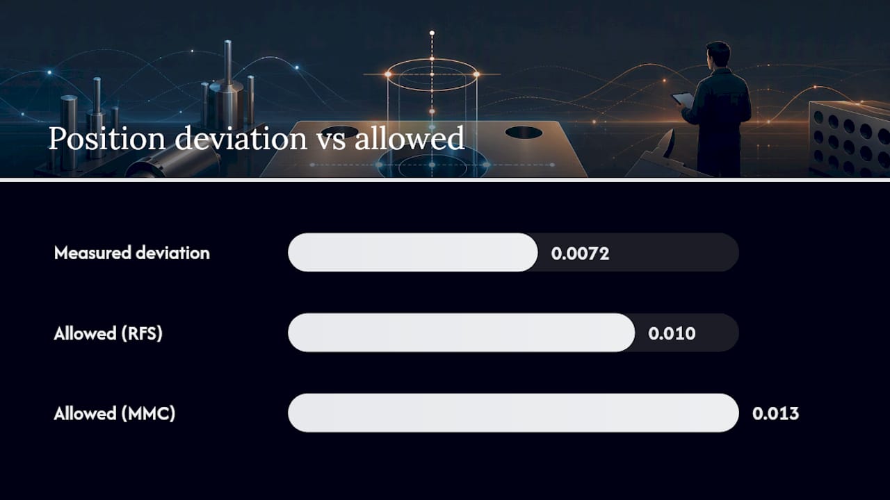
- Compute diametric deviation = 2 × √(0.003² + 0.002²) = 2 × √(0.000009 + 0.000004) = 2 × 0.0036 = 0.0072.
- The CMM also measures the actual hole diameter at ⌀0.251.
- Bonus tolerance = 0.251 − 0.248 = 0.003.
- Total allowed position tolerance = 0.010 + 0.003 = 0.013.
- Compare: 0.0072 measured versus 0.013 allowed. The hole passes, with margin to spare.
| Value | Without bonus (RFS logic) | With bonus (MMC) |
|---|---|---|
| Stated position tolerance | ⌀0.010 | ⌀0.010 |
| Bonus tolerance earned | 0 | 0.003 |
| Total allowed tolerance | ⌀0.010 | ⌀0.013 |
| Measured deviation | 0.0072 | 0.0072 |
| Result | Pass (0.0072 < 0.010) | Pass, with more margin |
Notice the part passes either way here, but that will not always be true. A hole measuring 0.0095 deviation would fail against a straight ⌀0.010 tolerance yet pass comfortably once bonus tolerance is added. That gap is exactly why MMC exists, and why ignoring it during inspection can scrap parts that actually function fine.
Accuracy in ΔX and ΔY depends entirely on how the center is extracted. A CMM using a best-fit circle or cylinder across multiple probe points at multiple depths gives a far more trustworthy axis than a two-point diameter check, especially on holes with any taper or barrel shape.
What Inspection Methods Work Best for Checking True Position?
CMM inspection with best-fit axis extraction is the standard for high-precision work. The machine probes multiple points around the hole’s circumference, sometimes at two or more depths to catch axis tilt, then fits a cylinder to those points mathematically. That fitted axis, not any single probe hit, becomes the measured center used in the diametric deviation formula.
Functional gaging takes a different route entirely. A gage pin machined to the virtual condition diameter either drops into the hole or it does not. If it fits, every hole checked with that pin is guaranteed to assemble with its mating part at worst-case conditions, full stop, no math required on the shop floor. Functional gaging is typically faster for high-volume production acceptance once the gage is built and qualified, while CMM remains the better tool for characterization, root-cause work, and any feature with complex geometry a simple pin cannot check.
Manual checks with calipers or pin gages have real limits. They catch gross size errors but cannot verify true position at all, since position is a relationship to a datum reference frame, not a single dimension. A caliper also cannot detect axis tilt through the material’s thickness the way a two-level CMM probe cycle can.
- CMM datum sequence must match the drawing’s datum order exactly, or the simulation is meaningless.
- Fixture the part the same way the datums specify, using the same contact points every time.
- Recheck gage pins periodically for wear, since a worn pin gives false passes on marginal holes.
Pro Tip: If a part fails position on the CMM but the functional gage says it fits, check the CMM’s datum simulation before you scrap anything. A programming mismatch between the drawing’s datum sequence and the CMM setup is a far more common cause of false rejects than an actual out-of-position hole.
What Drawing and Inspection Mistakes Cause the Most Scrapped Parts?
Most true position disputes trace back to one of four repeatable errors, and every one of them is fixable before a part ever hits the machine.
- Missing diameter symbol. A position value with no ⌀ defines two parallel planes, not a circle. Add the symbol whenever the toleranced feature is round and meant to take a round fastener.
- Double-controlling location. Some drawings still show ±0.002 coordinate dimensions alongside a position callout on the same hole. Pick one method. Coordinate tolerances plus a position frame create a legally ambiguous, mathematically conflicting requirement.
- Wrong datum sequence. Listing datums out of functional priority, or referencing a datum surface too small or unstable to locate the part repeatably, produces a reference frame that does not match how the part actually sits in its assembly.
- MMC where alignment demands precision. Applying MMC to a hole that needs tight, size-independent alignment, such as a dowel location between two precision-mated plates, trades away control the design actually needs. RFS belongs there instead.
Catching these four during drawing review costs minutes. Catching them after a production run costs a scrapped batch.
How Does a High-Volume Shop Keep True Position Under Control?
Holding ⌀0.010 or tighter across thousands of parts a day is not a design problem, it is a process control problem. Fixturing has to place every part against the same datum contact points, run after run, using reference plugs or locating pins that match the drawing’s datum scheme rather than whatever is convenient to hold.

MMC gets programmed deliberately, not applied as a default. When a hole’s function is clearance for a fastener, bonus tolerance gets built into both the CMM inspection routine and the functional gage design from the start, so the gage pin reflects true virtual condition rather than the bare position tolerance. Getting datum simulation wrong in either the gage or the CMM program is one of the most common causes of a mathematically correct but functionally irrelevant rejection.
Ongoing control matters as much as the initial setup:
- Pull periodic CMM samples off a running job and chart the center offsets over time.
- Track tool wear and drill or reamer life against the position data, not just a fixed change interval.
- Investigate drift immediately when a control chart trend appears, before parts start failing outright.
Pro Tip: Control charts on hole center offsets catch fixture wear and tool drift days before parts start failing position outright. By the time a CMM report shows an outright reject, the drift has usually been building for a while. Our tight tolerance machining guide covers the fixturing details that make this kind of monitoring possible.
Balancing Tight Position Tolerances Against Cost and Robustness
The instinct to tighten a position tolerance whenever a fit feels marginal is understandable, and it’s usually the wrong move. A tighter tolerance means slower inspection, more scrapped parts at the edges of the process distribution, and often a more expensive fixture just to hold the part still enough to measure it consistently. None of that buys anything if the actual functional requirement was satisfied by the tolerance already on the drawing.
The better question is almost always whether the mating design itself is fragile. A hole pattern that only works within a razor-thin position window is often a sign the clearance between hole and fastener is too small, not that the machinist needs tighter control. Widening a clearance hole by a few thousandths, or adding a chamfer to guide assembly, frequently solves what a tolerance change cannot.
Design and manufacturing should have this conversation before the drawing gets released, not after the first batch comes back with a disputed CMM report. A five-minute review of the tolerance specification approach at the design stage saves weeks of argument later.
— Andrew
Getting Tight True Position Holes Built and Verified Right
Our company has experience with high-volume, tight-tolerance work, and true position is a commonly programmed callout. Using CNC milling, turning, high-volume machining systems, and wire EDM for complex geometries, our processes aim to hold ⌀0.010 or tighter tolerances efficiently.

If your current supplier is scrapping parts on position when a functional gage says they fit, the fix usually lives in the datum simulation, not the machining itself, and that’s a problem worth solving before the next production run rather than after. Gage development and process characterization are integrated into prototype runs to address bonus tolerance and virtual condition from the start. Take a look at our precision parts manufacturing capabilities and request a quote or technical consultation to get your next tight-tolerance hole pattern reviewed before it goes to production.
Where to Verify True Position Standards and Formulas
For exact compliance language, check ASME Y14.5 directly rather than a secondhand summary. The GD&T Basics true position calculator is a solid quick-check tool for worked examples, and Xometry’s true position tolerance guide covers the calculation and datum relationships in more depth.