

Incorrectly specified machining tolerances create expensive problems: rework cycles drain resources, scrap rates climb, and production delays cascade through schedules. Manufacturing engineers face the challenge of balancing precision requirements against realistic process capabilities while maintaining cost efficiency. This guide delivers a practical roadmap to specifying machining tolerances that satisfy functional needs without inflating costs, covering industry standards, material considerations, measurement strategies, and common pitfalls to avoid.
Table of Contents
- Introduction To Machining Tolerances And Their Importance
- Standards And Frameworks For Specifying Tolerances
- Considering Material And Process Capability
Key takeaways
| Point | Details |
|---|---|
| Align tolerances with function | Specify tolerances based on part function and fit requirements, not arbitrary precision levels. |
| Use standardized notation | Apply ASME Y14.5 and GD&T symbols to eliminate ambiguity and improve cross-team communication. |
| Consider process capabilities | Match tolerance specifications to realistic machining process and material constraints. |
| Plan measurement early | Integrate inspection strategy during design to verify tolerances accurately and efficiently. |
| Avoid over-specification | Tighter tolerances escalate costs exponentially; specify only what function demands. |
Introduction to machining tolerances and their importance
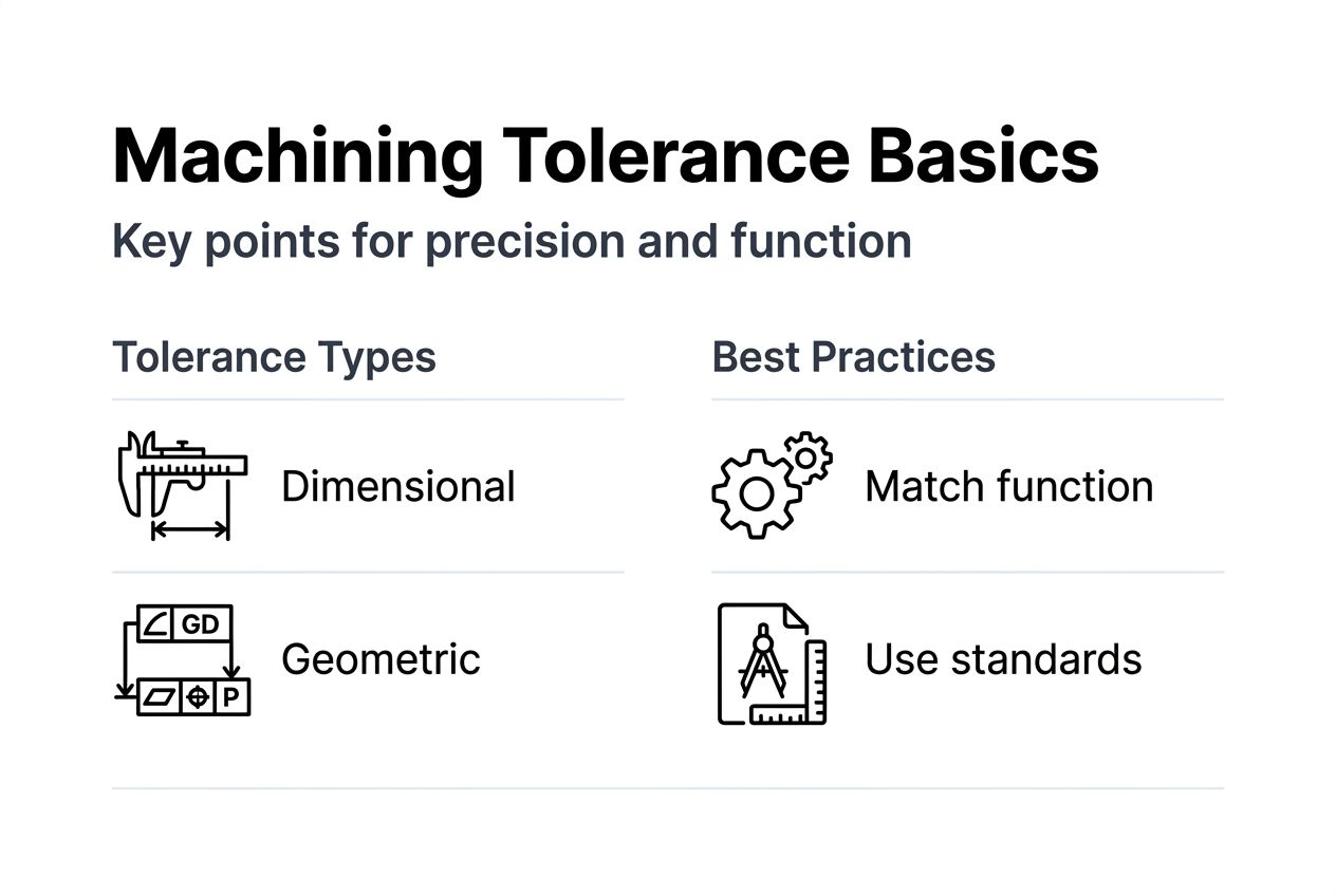
Machining tolerances define the permissible variation in dimensions and geometry of manufactured parts. Two primary categories exist: dimensional tolerances control linear measurements like diameter or length, while geometric tolerances govern form, orientation, profile, location, and runout characteristics.
Properly specified tolerances directly impact product quality, performance, and manufacturing economics. Aerospace components demand tolerances within 0.0005 inches to ensure flight safety and structural integrity. Automotive drivetrain parts require precise fits for smooth operation and longevity. Medical implants need exacting specifications to guarantee biocompatibility and patient safety.
When tolerances miss the mark, consequences multiply quickly. Over-specified tolerances that exceed functional requirements inflate production costs through unnecessary precision machining, longer cycle times, and higher scrap rates. Under-specified tolerances create parts that fail assembly, exhibit premature wear, or underperform in service. The ripple effects include:
- Increased scrap and rework consuming 5-15% of production budgets
- Delayed shipments damaging customer relationships and revenue
- Quality escapes reaching end users with warranty and liability implications
- Strained supplier relationships from unclear or inconsistent specifications
Balancing precision against manufacturability requires understanding both functional requirements and process realities. Engineers who master this balance deliver components that meet performance standards while optimizing production efficiency and cost.
Standards and frameworks for specifying tolerances
Industry standards provide a common language for tolerance specification, eliminating interpretation errors between design, manufacturing, and quality teams. The ASME Y14.5-2018 standard serves as the primary reference for dimensioning and tolerancing in North America, defining symbols, rules, and practices for mechanical drawings.
Geometric Dimensioning and Tolerancing (GD&T) extends beyond simple plus/minus dimensional tolerances. This symbolic language precisely defines form and relationship requirements:
- Flatness controls surface variation without reference to other features
- Perpendicularity defines angular relationship between features
- Position tolerance specifies location boundaries for holes and features
- Profile tolerance controls complex surface contours simultaneously
- Runout tolerance limits surface variation during rotation
Standardized notation delivers measurable benefits. Precision parts manufacturing quality improves when specifications use unambiguous symbols rather than ambiguous notes. Manufacturing teams interpret drawings consistently across shifts and facilities. Inspection procedures become straightforward when tolerances reference clear datums and measurement methods.
Cross-functional collaboration strengthens when everyone speaks the same technical language. Design engineers communicate intent without lengthy explanations. Machinists understand exactly which dimensions matter most. Quality inspectors know precisely how to verify compliance. Suppliers quote accurately because specifications leave no room for guesswork.
Adopting ASME Y14.5 principles requires initial training investment but pays dividends through reduced errors, faster production ramp-up, and fewer costly misunderstandings. Organizations that embrace standardized tolerance frameworks report 20-30% reductions in drawing revision cycles and clarification requests.
Considering material and process capability
Material properties fundamentally constrain achievable tolerance tightness. Aluminum machines easily and holds tolerances to 0.0005 inches routinely. Stainless steel’s work-hardening characteristics make maintaining tolerances below 0.001 inches more challenging. Titanium’s low thermal conductivity creates dimensional instability during cutting, limiting practical tolerance capability. [Firearm parts machining: ±0.001
Recommended
- Firearm parts machining: ±0.001″ tolerance ensures reliability | Machining Technologies
- Precision Parts Manufacturing: Maximizing Quality and Throughput | Machining Technologies
- Master Precision Machining Workflow for Firearms Components | Machining Technologies
- 7 Key Benefits of Precision Machining for Manufacturers | Machining Technologies
- Quality Control in Production Utah: Cut Defects 90% with AI