

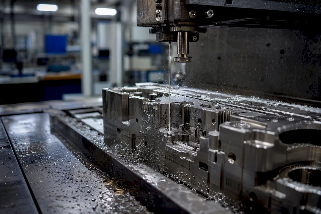
A single rough pass on a wire EDM machine typically holds about ±0.002". Add one or two skim passes and that band tightens to roughly ±0.0005" to ±0.0002". Push a job through multiple skims on a well-maintained, high-end machine and ±0.0001" or better becomes realistic. The number you get depends entirely on pass count, so the single most important thing to put on a drawing isn’t just a tolerance value. It’s the tolerance band paired with the required number of passes and the expected surface finish.
- Rough cut only: approximately ±0.002"
- One to two skim/trim passes: approximately ±0.0005" to ±0.0002"
- Multi-skim, premium equipment: approximately ±0.0001" or tighter
Pro Tip: If a quote doesn’t specify pass count, ask for it before you accept the tolerance number. A ±0.0005" callout means nothing without knowing whether it assumes one skim or four.
Key Takeaways
Wire EDM tolerance is a function of pass count, not a fixed machine specification, and every drawing callout should pair a tolerance band with the number of skim passes required to achieve it.
| Point | Details |
|---|---|
| Rough cut baseline | Expect approximately ±0.002" from a single rough pass before any finishing. |
| Skim passes tighten accuracy | One to two skim passes typically reach ±0.0005" to ±0.0002" depending on material. |
| Corner radius has a floor | Minimum practical internal radius is roughly half the wire diameter plus spark gap. |
| Stress relief prevents drift | Pre-cut stress relief and CMM verification protect thin or hardened parts from post-cut warping. |
| Machining Technologies validates in-house | Machiningtechllc documents CMM-verified tolerance targets across 20 million-plus parts produced annually from its Webster, Massachusetts facility. |
Table of Contents
- Wire EDM Tolerance Ranges and the Pass-Count Tradeoff
- What Process and Machine Settings Actually Drive Accuracy
- Corner Radius, Kerf, and Taper: The Design Limits You Can’t Ignore
- Specifying and Inspecting Wire EDM Tolerances on the Drawing
- Machining Technologies Evidence and Practitioner Notes
- How Thermal Distortion and Residual Stress Erode Tolerance
- Fixture and Workholding Practices That Protect Tight Tolerances
- Dielectric Fluid Condition and Its Effect on Cut Accuracy
- How Wire EDM Tolerances Compare to Other Precision Processes
- Common Tolerance Problems and How to Fix Them
- Selected Technical Papers and Client Resources
- What This Data Actually Tells Engineers to Do
- Get Wire EDM Parts Held to the Tolerance You Actually Specified
- Frequently Asked Questions
- Sources
Wire EDM Tolerance Ranges and the Pass-Count Tradeoff
Every wire EDM tolerance claim you’ll see in a quote or capability sheet is really a statement about how many times the wire revisits the cut. A rough cut, run at maximum power and feed rate to remove bulk material fast, lands around ±0.002" on typical shop equipment. That’s fine for a bracket bore or a die clearance slot where fit isn’t critical, but it’s nowhere close to what most precision applications need.
Adding a single skim pass, essentially a lighter, slower rerun of the same profile with reduced discharge energy, knocks that down to somewhere between ±0.0005" and ±0.0002" for most tool steels and aluminum alloys. Vendor capability pages commonly advertise standard tolerances in the 0.0005" to 0.0010" range as their baseline offering, with specialized shops quoting down to 0.0001" for parts that justify the extra cycle time. Titanium and other conductive but harder-to-cut alloys tend to sit at the looser end of any given pass count because spark erosion behaves differently at their thermal properties, so a titanium part run through the same three-pass sequence as a P20 tool steel block won’t necessarily land at the same number.
Here’s roughly what each additional pass buys you:
- Rough cut: bulk material removal, ±0.002", rough surface finish (often 4-6 µm Ra or worse)
- First skim: cuts geometric deviation substantially and starts refining the surface, moving toward ±0.0005"
- Second skim: further tightens dimensional accuracy and drops surface roughness noticeably
- Third+ skim: diminishing returns on dimension but continued surface finish improvement
Finishing operations, when wire dynamics and machine guiding are dialed in correctly, can reduce geometric deviations into the low-micron range, under 10 microns, which is where the tightest published tolerance claims come from. When you see a shop advertising numbers approaching four ten-thousandths of an inch, that’s a lab-condition, multi-skim result, not a rough-cut baseline. Ask what pass count backs any number before you commit a design to it.
What Process and Machine Settings Actually Drive Accuracy
Wire diameter, tension, and pulse control decide how close your part actually gets to the number on the quote. Thinner wire (0.004" to 0.006" diameter is common for fine detail work) cuts a smaller kerf and can hold a tighter minimum corner radius, but it’s also more prone to deflection under load, which shows up as bowing on tall or thick sections.
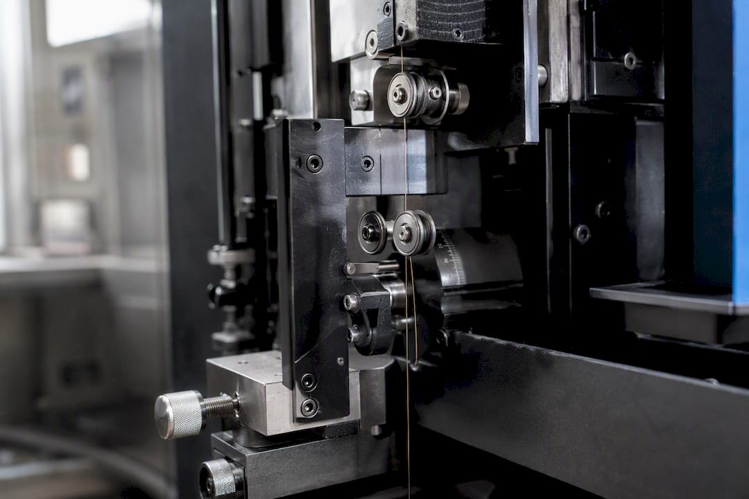
Wire tension and guiding accuracy matter more than most designers assume. Loose tension lets the wire vibrate mid-cut, and that vibration transfers directly into the part as wavy sidewalls or inconsistent width along the cut path. Tighter, well-controlled tension reduces that deflection and keeps the kerf consistent from top to bottom of the workpiece.
Pulse-on time, pulse-off time, servo feed rate, and flushing pressure govern wire wear rate, kerf stability, and surface finish simultaneously. A 2024 review of wire EDM geometric accuracy and surface quality found that thermophysical spark-gap behavior, wire dynamics, and flushing conditions govern kerf width and finish quality together, and that modern coated multi-layer wires expand the stable window where you can push speed without sacrificing dimensional control.
Corners and gear profiles need their own settings entirely. Taguchi-based experiments on corner and gear profile accuracy identified wire tension and pulse-on time as the two variables with the strongest influence on corner deviation, meaning a parameter set tuned for a straight wall will often undercut or round a sharp internal corner unless it’s adjusted specifically for that feature.
- Wire diameter selection sets your minimum practical corner radius and kerf width
- Tension and guide quality control vibration-driven wall waviness
- Pulse settings and flushing govern wire wear rate and surface finish together
- Controller trajectory compensation corrects for wire lag at direction changes
Modern controllers apply real-time trajectory compensation at direction changes, which helps hold corner geometry that would otherwise round off from wire lag alone.
Corner Radius, Kerf, and Taper: The Design Limits You Can’t Ignore
Design engineers run into wire EDM’s geometric limits most often at internal corners, thin webs, and thick sections that need a straight wall. The math is simple: your minimum practical internal corner radius equals roughly half the wire diameter plus the spark gap. Cut with 0.010" wire and a typical 0.001" spark gap per side, and you’re looking at a practical minimum internal radius near 0.006" to 0.008", not a true sharp corner. Specify a smaller radius and you’ll either get a rounded corner anyway or a program that dwells and burns an oversized pocket at the vertex.
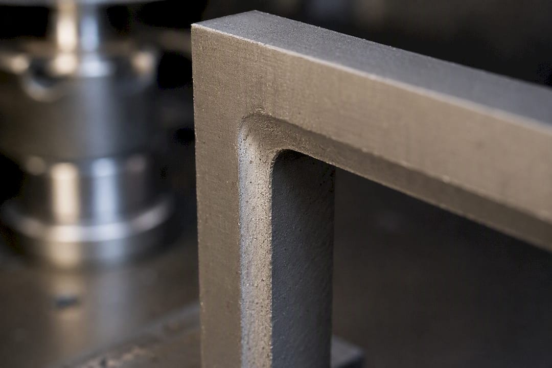
Kerf width, the total material removed by the wire path, needs to be accounted for in your offset programming rather than assumed away. A 0.010" wire with spark gap typically removes a slot around 0.012" to 0.014" wide, and any part with a press-fit or slip-fit mating feature needs that number baked into the nominal dimension, not treated as a rounding error.
| Feature | Typical minimum practical value |
|---|---|
| Internal corner radius (0.010" wire) | approximately 0.006"-0.008" |
| Kerf width (0.010" wire, standard spark gap) | approximately 0.012"-0.014" |
| Wire diameter for fine detail work | 0.004"-0.006" |
| Wire diameter for general production | 0.008"-0.012" |
Thick sections present a separate problem: taper. As material gets thicker, the discharge zone widens and wire deflection increases, producing a barrel or hourglass profile instead of a straight wall unless you slow the feed and add finishing offsets. For sections beyond roughly two inches, plan on multiple offset finishing cuts rather than a single skim, and expect the quote to reflect that added cycle time. When a feature needs a radius or kerf tighter than standard wire allows, micro-wire EDM (wire diameters under 0.003") or an alternative process is the honest answer, not a promise to “figure it out” at production time.
Specifying and Inspecting Wire EDM Tolerances on the Drawing
Get these five items on the drawing and the quote you get back will actually match what shows up on your dock. Skip any one of them and you’re negotiating tolerance after the parts are cut, which is the expensive way to find out what a shop can really hold.
- Tolerance band with pass count: state both together, e.g., “±0.0003” after 2 skim passes," never a bare tolerance number.
- Surface finish requirement (Ra): specify it explicitly since finish and dimensional tolerance move together through the pass sequence.
- Wire diameter assumption: note it if a specific kerf or corner radius depends on it.
- Material and thickness note: call out alloy and section thickness, since both change achievable accuracy.
- Inspection method and sample size: state CMM verification with a defined probe plan, plus first-article sample requirements.
For inspection, a CMM probe plan with a clear datum strategy catches deviations that a caliper simply can’t resolve at these tolerances. Require a first-article CMM report on any job with a tolerance tighter than ±0.001", and state your accepted measurement uncertainty rather than assuming the supplier’s gauge resolution matches your requirement. A technical primer on precision machining tolerances and inspection practices is a useful reference if your team is standardizing RFQ language across multiple part families.
Pro Tip: Paste this into every wire EDM RFQ: tolerance band + pass count, Ra target, wire diameter assumption, material/thickness, and required first-article CMM report with defined probe points. Suppliers who balk at any one of these five items are telling you something.
For a deeper walkthrough of drawing callouts and measurement strategy, Machiningtechllc’s guide on how to specify machining tolerances for precision covers datum selection and sample sizing in more depth than fits here.
Machining Technologies Evidence and Practitioner Notes
Machining Technologies LLC has run high-precision wire EDM work out of its 70,000 square foot Webster, Massachusetts facility since 1985, with dedicated wire EDM capability built specifically for tight-tolerance aerospace, defense, and firearm components. That’s four decades of production data behind the tolerance numbers this article describes, not theoretical best cases pulled from a spec sheet.
Production experience backs the numbers cited throughout this piece:
- Rough cut and skim-pass tolerance bands match what shows up in day-to-day quoting at scale
- In-house CMM verification and first-article inspection are standard practice on tight-tolerance orders, not an upcharge
- High-throughput capability (the company reports producing over 20 million parts annually) means parameter sets for common material-thickness-feature combinations are already validated, not re-qualified from scratch on every job
The gap between a published tolerance capability and a repeatable production tolerance is where most quoting disappointments happen. A shop that can document its CMM validation process on tight-tolerance runs is a shop that isn’t guessing.
Full capability details and Wire EDM-specific parameter guidance are available on Machiningtechllc’s wire EDM overview page.
How Thermal Distortion and Residual Stress Erode Tolerance
Wire EDM removes material through localized electrical discharge, and that process heats the workpiece unevenly even with aggressive flushing. Heat-affected zones form along the cut path, and if the stock already carries residual stress from prior rolling, forging, or heat treatment, cutting through it releases that stress unevenly as the part separates from the surrounding material.
The practical result is a part that measures fine on the machine but relaxes into a slightly different shape an hour later. Thin, high-aspect-ratio parts show this most visibly, sometimes bowing or twisting measurably once released from the fixture. Thicker sections that concentrate more discharge energy see wider heat-affected zones and correspondingly larger distortion risk if the material wasn’t stress-relieved before cutting.
Stress relief before the cut is the most reliable mitigation, and it matters most on hardened tool steels and aerospace alloys where post-cut movement of even a few thousandths ruins a fit. For aerospace-grade parts specifically, combining pre-cut stress relief with finishing passes and CMM verification is the recommended sequence to avoid the assembly fit failures that residual-stress-driven curvature can cause.
If your part geometry is thin, asymmetric, or cut from bar stock with a known heat-treat history, build a stress-relief step into the process plan rather than discovering the distortion at final inspection. Rough cutting a rough shape first, stress-relieving, and then finishing to final dimension is a common sequence for parts where distortion risk is high and tolerance margin is thin.
Fixture and Workholding Practices That Protect Tight Tolerances
A wire EDM part is only as accurate as the fixture holding it during the cut, because any movement between rough cut and finish skim shows up directly as dimensional error. The wire itself exerts almost no cutting force, which is one of wire EDM’s advantages, but that doesn’t eliminate workholding as a variable. Thermal expansion during the cut and stress release as material separates both move the part relative to the fixture if the holding strategy doesn’t account for them.
Datum consistency across the rough cut and every subsequent skim pass matters more here than in most machining processes. If the part shifts even slightly between passes, each skim cuts relative to a slightly different reference, and the tolerance band you were targeting quietly widens without any single step looking wrong on its own.
A few practices consistently hold up in production:
- Locate from the same datum surfaces for rough and skim passes, never re-zeroing on a secondary feature mid-job
- Use minimal clamping force on thin or delicate sections to avoid introducing elastic deformation that releases after the cut
- Support long or thin workpieces to prevent sag that changes the effective cut plane
- Allow parts with known residual stress to stabilize between rough and finish passes when the tolerance justifies the added cycle time
Tombstone fixtures and dedicated EDM vises designed for repeatable datum location outperform generic clamping setups on any job with a tolerance tighter than ±0.0005", simply because they remove the operator-dependent variability of manual part alignment between passes.
Dielectric Fluid Condition and Its Effect on Cut Accuracy
Deionized water is the standard dielectric for wire EDM, and its condition, specifically resistivity, temperature, and contamination level, directly affects spark consistency and therefore dimensional repeatability. Water that’s too conductive changes how the discharge behaves at the spark gap, and water carrying accumulated debris from prior cuts increases the risk of secondary discharges that widen the kerf unpredictably.
Flushing pressure and flow rate work alongside dielectric condition to clear debris from the cut zone. Insufficient flushing lets removed material redeposit in the gap, causing arcing that damages surface finish and introduces localized dimensional error exactly where you don’t want it, at a corner or a critical wall. The 2024 geometric accuracy review notes that flushing conditions rank alongside pulse energy and wire dynamics as primary drivers of kerf stability and surface quality.
Thicker parts need proportionally more attention to flushing because debris has farther to travel out of the cut zone, and dielectric temperature tends to climb over longer cut cycles unless the system’s cooling and filtration keep pace. Shops running high-volume wire EDM typically monitor resistivity continuously and maintain scheduled filter and deionizer resin changes rather than waiting for a visible quality problem to trigger maintenance. That’s a maintenance discipline question as much as a machine settings question, and it’s worth asking a supplier about directly if a job’s tolerance leaves no room for kerf drift over a long cutting cycle.
How Wire EDM Tolerances Compare to Other Precision Processes
Wire EDM’s tolerance advantage shows up specifically on hardened materials and complex internal geometry, not as a universal win over every precision process. Grinding often matches or exceeds wire EDM’s best-case dimensional accuracy on flat or simple cylindrical features, and it does so faster when the geometry allows a straight grind path. Where wire EDM pulls ahead is on hardened tool steel with intricate profiles, internal corners, or gear tooth forms that a grinding wheel physically can’t access.
CNC milling and turning generally hold comparable or looser tolerances than a multi-skim wire EDM pass, typically in the ±0.0005" to ±0.001" range on well-maintained equipment, but milling cuts far faster on straightforward geometry and handles blind pockets that wire EDM cannot, since wire EDM always cuts through the material and can’t create a blind cavity. That single limitation decides the process choice more often than tolerance does: if the feature needs to be a through-cut in a conductive material, wire EDM’s accuracy advantage on hard materials and tight internal geometry makes it the practical choice regardless of what a comparably toleranced mill setup could achieve on an open-pocket version of the same part.
Sinker EDM fills the blind-cavity gap that wire EDM can’t reach, at somewhat looser typical tolerances. For a part needing both a blind feature and a tight-tolerance through profile, expect a combination process plan rather than a single method covering the whole geometry.
Common Tolerance Problems and How to Fix Them
Taper on thick sections is the defect that catches the most designers off guard, showing up as a barrel or hourglass profile where the top and bottom of a cut don’t match the middle. It stems from wire deflection under discharge pressure over a longer engagement length. The fix is a slower feed rate combined with additional offset finishing passes rather than trying to force a single-pass solution on anything beyond roughly two inches of thickness.
Corner rounding where a drawing calls for a sharp internal vertex is a geometry problem, not a machine defect: no standard wire diameter can cut a true zero-radius internal corner, and the fix is adjusting the drawing to the practical minimum radius your wire size actually allows, not chasing a tighter machine setting.
Wavy or inconsistent sidewalls typically trace back to wire tension or guide wear, and the fix is mechanical maintenance, checking guide condition and tension calibration, rather than a programming change. Post-cut warping or bowing, especially on thin parts, points to residual stress release, and the fix lives upstream of the cut: stress relief before machining, not adjustment after the fact.
Dimensional drift over a long production run, where early parts measure in tolerance and later parts creep outside it, usually traces to dielectric degradation or wire wear accumulating across the run. Scheduled dielectric maintenance and wire spool changes at defined intervals prevent this from surfacing as a supplier quality escape on a customer’s dock.
Selected Technical Papers and Client Resources
- Corner and shape accuracy study covering Taguchi-based parameter optimization for gear and fin profiles
- Geometrical accuracy prediction study on finishing-pass effects for tool steel
What This Data Actually Tells Engineers to Do
The research consistently points to one conclusion that most casual tolerance discussions skip: pass count and parameter selection matter more than the machine’s marketed capability. A shop advertising ±0.0001" and a shop advertising ±0.0005" may own nearly identical equipment; the difference is how many skim passes and how much stress-relief discipline goes into the job. That’s the gap conventional advice glosses over when it treats tolerance as a static spec sheet number instead of a process outcome.
The overlooked priority is corner and feature-specific parameter tuning. Most engineers assume a single machine setting produces a uniform tolerance across an entire part, but the Taguchi research on corner accuracy makes clear that straight walls and internal corners behave differently under the same nominal settings. A drawing that specifies one tolerance for the whole profile without flagging corner features as a separate concern is setting up a mismatch between what’s promised and what’s measured.
If you take one thing from this article, make it the RFQ checklist, not the numbers. Numbers change by material and machine; the discipline of demanding pass count, finish, and CMM verification on paper does not.
Get Wire EDM Parts Held to the Tolerance You Actually Specified
Reading a tolerance callout on a drawing is one thing. Getting a supplier to actually hit it, consistently, across a production run, is where most engineers get burned. Machiningtechllc runs dedicated wire EDM capability inside its 70,000 square foot Webster, Massachusetts facility, with the pass-count discipline and CMM verification practices this article describes built into standard production, not offered as a premium add-on.

That matters most for engineers who’ve been quoted a tight tolerance and later found production parts drifting outside it: the fix is a supplier that documents its inspection process before the job starts, not after a customer complaint. Machiningtechllc’s wire EDM capability page covers the specific tolerance bands and materials the shop runs daily, and its contract machining benefits page walks through what outsourcing a tight-tolerance run looks like for OEMs weighing in-house versus contracted production. Submit a print with your tolerance band, pass count, and finish requirement, and get a quote that already accounts for the inspection plan.
Frequently Asked Questions
What tolerance can wire EDM realistically hold on a rough cut?
A single rough pass typically holds around ±0.002". That figure assumes no skim passes and a standard wire diameter; it’s a starting point, not a finished-part tolerance.
How many skim passes does a ±0.0005" tolerance usually require?
Most shops reach ±0.0005" to ±0.0002" with one to two skim passes on common tool steels and aluminum, though titanium and other harder-to-cut alloys may need an additional pass to hit the same band.
Can wire EDM cut a sharp internal corner with zero radius?
No. The minimum practical internal radius is roughly half the wire diameter plus the spark gap, so a true zero-radius corner isn’t achievable with any standard wire size.
Does wire EDM tolerance change with material thickness?
Yes. Thicker sections widen the effective discharge zone and increase wire deflection, which raises taper risk unless the feed rate is slowed and extra finishing offsets are added.
What inspection method should I require for tight-tolerance wire EDM parts?
Require a CMM report with a defined probe plan and datum strategy, plus a first-article inspection sample on any job tighter than ±0.001", rather than relying on caliper measurements alone.
Can wire EDM create a blind pocket instead of a through-cut?
No. Wire EDM always cuts completely through the workpiece since the wire has to pass all the way through the material. Blind cavities require sinker EDM instead.
Sources
- Study of Corner and Shape Accuracies in Wire Electro-Discharge Machining of Fin and Gear Profiles and Taper Cutting
- Prediction of the Geometrical Accuracy of the Machined Surface of the Tool Steel EN X30WCrV9-3 after Electrical Discharge Machining with CuZn37 Wire Electrode
- Wire electrical discharge machining technology: review on geometric accuracy and surface quality