
TL;DR:
- Industrial prototyping creates pre-production models to test design fit, function, and manufacturability before full production. It involves different fidelity levels and methods like 3D printing and CNC machining, depending on testing goals. Proper planning and matching prototypes to specific objectives improve accuracy, speed, and cost efficiency in product development.
Industrial prototyping is the process of creating pre-production physical models that test and validate engineering designs before committing to mass manufacturing. Every serious manufacturing prototyping guide starts here: prototypes expose fit, function, and manufacturability issues at a fraction of the cost of a production tooling mistake. Whether you work in aerospace, defense, or industrial machinery, the principles of this industrial prototyping guide apply directly to your development cycle. The goal is always the same: build, test, learn, and refine before the stakes get expensive.
What does an industrial prototyping guide cover?
Industrial prototyping spans the full range of pre-production modeling, from rough concept models to manufacturing validation builds. The industry recognizes two distinct fidelity levels. Early prototypes use cheaper, faster fabrication to answer geometry and assembly questions quickly. Manufacturing validation prototypes use production-intent materials and tooling to confirm the design performs under real conditions. Treating both stages the same is one of the most common and costly mistakes in product development.
The standard tolerance benchmark for manufacturing validation prototypes is ±0.25mm. That figure is not arbitrary. Parts built outside that range produce misleading test results, which means your validation data cannot be trusted when you move to production. Knowing which fidelity level applies to each build phase is the foundation of every effective prototyping workflow.
What tools and materials do you need for prototyping?
The right tools depend on what question your prototype needs to answer. Digital tools come first. CAD software such as SolidWorks or CATIA generates the geometry, while simulation platforms test stress, thermal load, and fluid behavior before a single part is built. Getting this step right reduces physical build cycles.
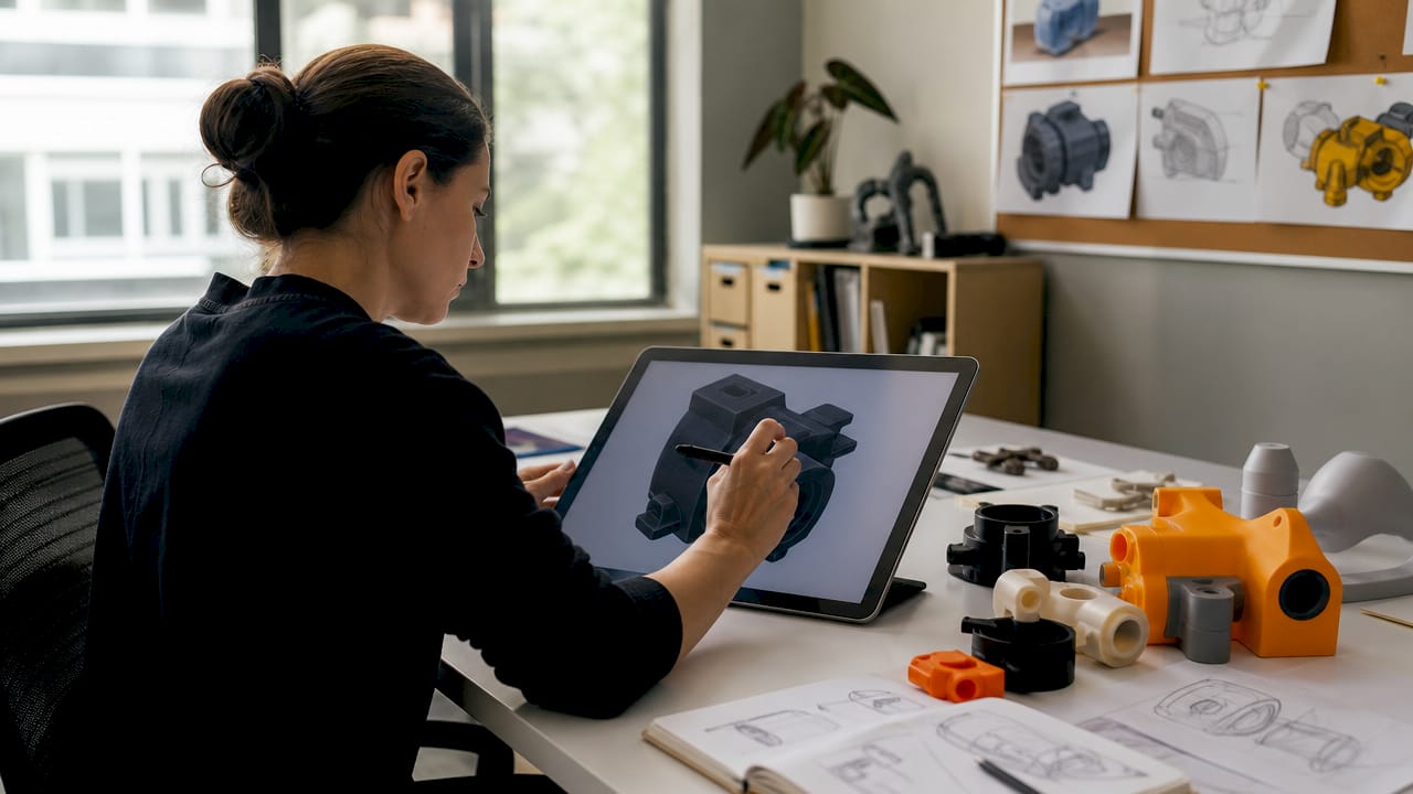
Additive manufacturing covers the widest range of early-stage needs. Rapid prototyping methods include Fused Deposition Modeling (FDM) for low-cost geometry checks, Stereolithography (SLA) for fine surface detail, and Selective Laser Sintering (SLS) for functional nylon parts with real mechanical properties. Each technology trades speed, cost, and material capability differently.
Subtractive processes, particularly CNC machining, produce parts with tighter tolerances and better surface finishes than most additive methods. CNC milling and turning are the standard choice when a prototype must behave like a production part in terms of strength and dimensional accuracy. Wire EDM adds value for complex geometries and hardened materials.
| Method | Best application | Relative cost | Speed |
|---|---|---|---|
| FDM 3D printing | Geometry and fit checks | Low | Fast |
| SLA 3D printing | Surface detail and aesthetics | Low to medium | Fast |
| SLS 3D printing | Functional nylon components | Medium | Medium |
| CNC machining | Tight tolerance, production-like parts | Medium to high | Medium |
| Vacuum casting | Low-volume functional parts | Medium | Medium |
| Wire EDM | Complex geometry, hardened materials | High | Slow |
Material selection follows method selection. Early builds use PLA, ABS, or urethane resins. Validation builds require aluminum alloys, stainless steel, or engineering-grade polymers that match production specifications.
Pro Tip: Never select a prototyping method because it is familiar. Select it because it answers the specific question your current build phase requires.
How do you plan and execute the prototyping process?
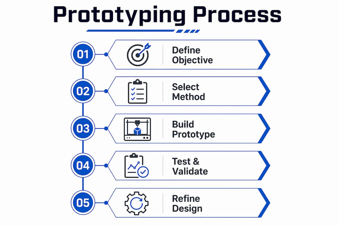
Effective execution starts with a single, clear learning objective for each build. Selecting prototyping methods should be driven by learning goals such as geometry verification, assembly fit, or material behavior, not by technology preference or habit. Write the test question before you write the build order.
The standard execution sequence runs as follows:
- Define the learning objective. State exactly what the prototype must prove or disprove.
- Select the method. Match the fabrication process to the test goal and fidelity requirement.
- Build the prototype. Use the fastest path to a testable part, not the most polished one.
- Test against the objective. Run mechanical, thermal, ergonomic, or assembly tests as required.
- Document findings. Record what passed, what failed, and what changed.
- Refine and rebuild. Apply findings to the next iteration. Repeat until the objective is met.
- Advance fidelity. Move to production-intent materials and processes for final validation.
Early building and testing yield more knowledge than extensive upfront planning. This is not a license to skip planning. It means that a physical part in hand reveals problems that no CAD review will catch. The build-test-refine cycle is where real engineering decisions get made.
Stakeholder management runs parallel to the technical cycle. Engineers and project managers must align on what each prototype stage is designed to prove. A concept model is not a finished product. Presenting it without context creates false expectations and pressure to over-refine early builds before the design is stable.
Pro Tip: Assign a single owner to each prototype iteration. Shared ownership of test outcomes creates ambiguity. One person signs off on what was learned and what changes next.
For teams managing OEM prototyping workflows, the step-by-step approach above maps directly to faster decision cycles and fewer costly late-stage revisions.
What quality control measures apply to prototypes?
Quality control in prototyping is not about perfection. It is about measuring the right things at the right stage. Manufacturing validation prototypes must demonstrate performance under realistic conditions, which requires close attention to materials, finishes, and assembly methods. A prototype that looks like a production part but is made from the wrong material produces unreliable test data.
The ±0.25mm precision tolerance standard applies specifically to assemblies where fit and function depend on dimensional accuracy. For early concept models, tolerances can be looser. For final validation builds, they must match or approach production specifications. Knowing which standard applies to each stage prevents wasted effort and misleading results.
Testing methods vary by prototype stage:
- Mechanical testing: Load, fatigue, and stress tests confirm structural performance.
- Thermal testing: Heat cycling and thermal imaging verify material behavior under operating temperatures.
- Assembly verification: Physical fit checks confirm that mating parts assemble correctly within tolerance.
- Ergonomic review: Hands-on evaluation of size, weight, and user interaction for operator-facing components.
- Surface finish inspection: Visual and tactile checks confirm that finish meets functional or cosmetic requirements.
| Prototype stage | Tolerance target | Primary test focus |
|---|---|---|
| Concept model | ±1.0mm or looser | Geometry, proportion, basic fit |
| Functional prototype | ±0.5mm | Mechanical performance, assembly |
| Manufacturing validation | ±0.25mm | Full performance, production materials |
Tight tolerance machining becomes the critical capability at the validation stage. Parts that cannot hold ±0.25mm in prototype form will not hold it in production either.
What are the most common industrial prototyping mistakes?
The most damaging mistake is over-polishing early prototypes. Effective prototyping requires managing stakeholder expectations and focusing on the quickest path to testing the core assumption. Spending three weeks perfecting the surface finish on a concept model delays the real test by three weeks. That delay compounds across every iteration.
Post-processing time is the second most underestimated variable. Sanding, support removal, and surface finishing add significant lead time beyond the build itself. A part that prints in eight hours may require two days of post-processing before it is testable. Project plans that ignore this create schedule pressure that forces shortcuts in testing.
Other common failures include:
- Wrong method for the test goal. Using FDM for a thermal performance test produces meaningless results. Match the process to the question.
- Skipping assembly verification. Individual parts that meet tolerance can still fail to assemble correctly. Test the assembly, not just the components.
- Treating all iterations equally. Early builds should be fast and cheap. Validation builds should be thorough and production-representative. Applying validation-level rigor to concept builds wastes time and money.
- Ignoring AI-driven workflow tools. Manufacturing teams that understand why manufacturers adopt AI now are compressing design-to-prototype cycles in ways that purely manual workflows cannot match.
Pro Tip: Build a post-processing time estimate into every prototype schedule before the build starts. Add it as a fixed line item, not an afterthought.
Key Takeaways
Effective industrial prototyping requires matching fidelity level, method, and tolerance standard to the specific validation goal of each build phase.
| Point | Details |
|---|---|
| Define the learning objective first | Every prototype build must answer one specific question before fabrication begins. |
| Match method to test goal | FDM, SLA, SLS, CNC, and EDM each serve different fidelity and accuracy needs. |
| Apply ±0.25mm at validation stage | Manufacturing validation prototypes must hold this tolerance to produce reliable test data. |
| Account for post-processing time | Sanding, support removal, and finishing add significant lead time beyond the build itself. |
| Iterate fast, validate thoroughly | Early builds should be cheap and quick; final validation builds must use production-intent materials. |
Why I think most teams prototype in the wrong order
Most teams I have seen run into the same problem: they spend too long on the first prototype and not long enough on the second and third. The instinct to present something polished before it has been tested is understandable. Stakeholders want to see progress. But a polished prototype that has not been tested is just an expensive model.
The teams that prototype well treat the first build as a question, not an answer. They build it fast, break it deliberately, and learn something specific. Then they build again. The iteration speed is what separates teams that hit production on schedule from those that are still revising tooling six months late.
The other thing I have seen consistently: the gap between engineering and manufacturing gets widest during the prototype phase. Engineers optimize for test results. Manufacturing teams optimize for producibility. Both are right. The fix is to bring manufacturing input into the prototype planning stage, not after the design is locked. Machiningtechllc has operated this way since 1985, and the difference it makes in final part quality is not subtle.
The custom component prototyping process works best when engineering and manufacturing share the same build objectives from the start. That alignment is not a soft skill. It is a schedule and cost variable.
— Andrew
Precision manufacturing support from Machiningtechllc
When your prototype validation confirms the design is ready for production, the transition to full-scale manufacturing should not introduce new variables. Machiningtechllc provides contract machining services that carry prototype-proven designs directly into high-volume production, with the same dimensional standards your validation builds required.
Operating from a 70,000 square foot facility in Webster, Massachusetts, Machiningtechllc runs Hydromat systems, CNC milling, CNC turning, and wire EDM across aerospace, defense, and industrial machinery programs. The team has produced over 20 million parts annually with on-time delivery as a core commitment. For OEMs and industrial manufacturers that need a partner who understands both the prototype phase and the production ramp, Machiningtechllc delivers the precision and throughput that bridges both.
FAQ
What is industrial prototyping?
Industrial prototyping is the process of building pre-production physical models to validate fit, function, and manufacturability before committing to full production tooling. It spans from early concept models to manufacturing validation builds using production-intent materials.
What tolerance standard applies to manufacturing validation prototypes?
Manufacturing validation prototypes must maintain tolerances within ±0.25mm to produce accurate fit and function test results. Parts built outside this range generate unreliable data that cannot be trusted for production decisions.
Which rapid prototyping methods are most common?
The most widely used rapid prototyping methods are FDM, SLA, and SLS for additive manufacturing, plus CNC machining and vacuum casting for subtractive and hybrid approaches. Method selection depends on material requirements, budget, and the specific test objective.
How does 3D printing fit into industrial prototyping?
3D printing in prototyping covers early geometry checks with FDM, surface detail with SLA, and functional nylon parts with SLS. It is best suited for early-stage builds where speed and low cost matter more than production-grade material properties.
Why is post-processing time frequently underestimated?
Post-processing steps such as sanding, support removal, and surface finishing can add days to a prototype schedule beyond the build time itself. Project plans that treat build time as total lead time consistently create schedule pressure and force shortcuts in testing.