

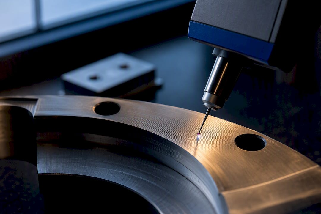
A surface finish chart converts and cross-references roughness values (Ra, Rz, RMS, micro-inches, micrometers) so you can translate a drawing callout into a real, measurable surface. The tables that matter follow three references: ASME B46.1 for parameters and measurement, ASME Y14.36 for drawing symbols, and ISO 4287 for profile parameters. Below you’ll find conversion tables, spec examples, and process-achievable ranges.
TL;DR:
- Converting surface roughness values requires matching parameters with the correct units, cutoff lengths, and measurement directions to avoid costly misinterpretations.
- Ra alone does not fully define surface functionality, as parameters like Rsk or Rz provide critical peaks or valleys information essential for sealing, wear, or fatigue performance.
- Differences in measured Ra values often stem from mismatched cutoff lengths and filtering methods rather than instrument inaccuracies.
- Specifying an overly tight finish, such as 8 microinches, increases cost without functional benefits unless the surface quality directly impacts performance or sealing.
- Use process capability data and function-focused parameters to set realistic, effective surface finish specifications rather than relying solely on arbitrary Ra targets.
Table of Contents
- Surface Finish Chart: Ra, RMS, Rz, and Micro-Inch Conversions
- Roughness, Waviness, and Lay: The Parameters Behind the Chart
- Cutoff, Sampling Length, and Why Two Labs Get Different Numbers
- What Common Finish Callouts Actually Mean in Production
- Drawing the Callout: ASME Symbols and Full Specification Examples
- What a High-Volume Machining Shop Sees on the Floor
- Why Most Surface Finish Specs Are Wrong From the Start
- Sources
Surface Finish Chart: Ra, RMS, Rz, and Micro-Inch Conversions
Most surface finish confusion starts with unit mismatches. A drawing marked “32” almost always means 32 microinches Ra, not 32 micrometers, and mixing those two up on a quote can turn a mirror-ground surface into a scrap part. The Engineers Edge conversion tables remain one of the more practical references for translating between systems, and the numbers below reflect that standard cross-reference.
Ra and RMS are not interchangeable, even though shops often treat them that way. RMS (Rq) squares the deviations before averaging, so it weights larger peaks and valleys more heavily than Ra does. Ra to Rz is even less predictable because Rz depends on how many sampling lengths you average and which peak-to-valley definition your instrument uses.
Here’s what the numbers assume:
- All values use a standard cutoff length appropriate to the Ra range (typically 0.8 mm for Ra between 0.1 and 2 μm).
- Conversions assume a random, isotropic surface texture, not a directional lay pattern like turning marks.
- RMS figures are approximate. Actual Rq-to-Ra ratios shift with surface type, sometimes reaching 1.2 or higher on highly skewed surfaces.
Roughness, Waviness, and Lay: The Parameters Behind the Chart
A surface finish chart only tells half the story unless you understand what it’s measuring. ASME B46.1 breaks surface texture into three distinct layers: roughness (fine, closely spaced irregularities from the cutting tool or abrasive), waviness (longer-wavelength deviations from machine vibration, deflection, or fixturing), and lay (the dominant direction of the surface pattern, like the helical marks from a lathe).
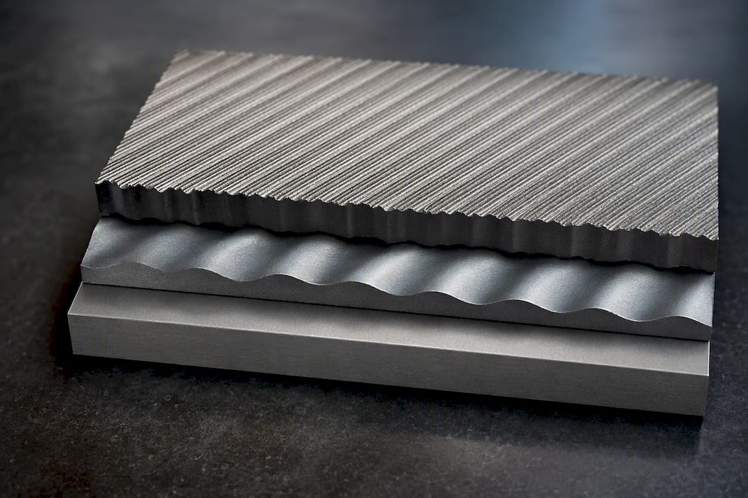
Confusing roughness with waviness is a common and expensive mistake. A part can measure a beautiful Ra 16 microinch and still leak at a seal interface because nobody controlled waviness.
The parameter glossary you’ll actually use on a drawing:
- Ra — arithmetic average roughness; the default, most-quoted parameter.
- Rq (RMS) — root-mean-square roughness; more sensitive to outlier peaks than Ra.
- Rz — average of the five highest peaks and five deepest valleys within the sampling length.
- Rt — total peak-to-valley height across the entire evaluation length.
- RSm — mean spacing of profile irregularities; controls feel and optical scatter.
- Rsk (skewness) — describes whether the surface has more peaks or more valleys.
- Rku (kurtosis) — describes how sharp or spread the peak distribution is.
Pro Tip: Ra is an average, so two surfaces with identical Ra values can behave completely differently in service. A surface with deep, isolated scratches on an otherwise smooth field can carry the same Ra as an evenly textured one, but the scratched surface will fail a seal or fatigue test first. When function depends on peak shape, such as sealing, wear, or fatigue-critical surfaces, specify Rsk or Rku alongside Ra, as ISO 4287’s parameter guidance recommends.
Cutoff, Sampling Length, and Why Two Labs Get Different Numbers
Two profilometers can measure the same part and report different Ra values, and the cause is almost always a mismatched cutoff, not a bad instrument. The cutoff length (denoted λc, or “short cutoff, s”) separates roughness from waviness by filtering out longer wavelengths. A shorter cutoff captures finer detail; a longer one folds waviness into the roughness reading.
The evaluation length is typically five times the cutoff, giving you five sampling lengths to average. Bandwidth, the ratio between the long cutoff and short cutoff, determines what range of wavelengths your instrument actually reports. Choose a cutoff that’s smaller than the feature you’re trying to control, or you’ll average it away.
Here’s the checklist worth putting directly on the drawing or inspection callout:
- Parameter (Ra, Rz, Rq, etc.)
- Numeric value and units (μin or μm)
- Cutoff length (λc), typically 0.08, 0.25, 0.8, or 2.5 mm
- Evaluation/sampling length (usually 5× cutoff)
- Measurement direction relative to lay
Pro Tip: If your incoming inspection reports fail to match your CAM shop’s numbers, the filter setting is the first thing to check, not the gauge calibration. Request that both sides use a Gaussian filter per ASME B46.1 and a skidless stylus baseline, since skid-type gauges mechanically filter out waviness before the software ever sees the data.
What Common Finish Callouts Actually Mean in Production
A microinch callout around a few hundred microinches is common for general-purpose machined surfaces, non-mating faces, structural brackets, and places where appearance and friction are less critical. A lower microinch finish is generally used on machined faces that mate but don’t seal, like bolted flanges or bearing shoulders with a press fit. Even finer microinch finishes are typical for sealing surfaces, close sliding fits, and fatigue-sensitive features.
Process capability by method, in typical Ra terms:
- Turning and milling processes typically achieve a range of microinch finishes appropriate for various levels of precision, with finer finishes possible using sharp tooling and low feed rates.
- Grinding is commonly used for finishes finer than general turning tolerances.
- Honing is often applied on cylinder bores and hydraulic components for finer finishes.
- Polishing and lapping are reserved for very fine finishes used in optics, seals, and mirror applications.
- Wire EDM can produce a range of finishes depending on skim-cut passes, often with a distinctive non-directional surface pattern.
Specifying an 8 microinch finish on a non-critical bracket doesn’t make the part better. It adds a secondary lapping operation, extra cycle time, and a cost jump that has nothing to do with how the part actually functions.
Drawing the Callout: ASME Symbols and Full Specification Examples
The basic surface texture symbol under ASME Y14.36 is a checkmark shape, modified with additional marks and text to indicate material removal requirements, lay direction, and numeric limits. A bare checkmark means “surface texture applies, method unspecified.” A checkmark with a circle means “no material removal permitted,” which you’d use on a cast or forged surface left as-is.
Three callouts you can copy directly onto a drawing:
| Callout | Meaning |
|---|---|
| Ra 32 / λc 0.8mm | Ra 32 microinch max, standard cutoff length |
| Ra 16 / Rz 63 / ⊥ lay | Dual parameter: Ra and Rz limits, lay perpendicular to indicated direction |
| Ra 8 / λc 0.25mm / no burrs | Fine finish with tighter cutoff plus a burr-free note for sealing surfaces |
Add a waviness limit only when the feature genuinely needs one, such as an optical flat or a static seal face. Stacking every parameter on every surface just clutters the drawing and confuses your supplier.
What a High-Volume Machining Shop Sees on the Floor
At Machining Technologies LLC, Hydromat rotary transfer machines routinely hold consistent 63 to 125 microinch finishes on high-volume turned components, while precision grinding handles anything below 32 microinches. Wire EDM produces moderate finishes on geometry that milling or turning can’t reach, and secondary post-processing covers the rest when a spec calls for polish or lapping.
For inspection, request that filter settings and sample count travel with every report, not just the final Ra number.
Pro Tip: Before you lock a finish spec, ask your machining partner for a process-capability statement instead of guessing at what “looks smooth enough.” A function-driven spec, backed by actual process data, avoids both scrap risk and the padded cost of an unnecessarily tight callout.
Why Most Surface Finish Specs Are Wrong From the Start
The biggest failure in surface finish specification isn’t picking the wrong number. It’s picking a number without asking what it needs to do. Engineers default to Ra because it’s the parameter everyone learned in school, then reach for a tighter value than the application requires because tighter feels safer. That instinct runs backward. A sealing surface needs peak control, not just an average, and a bearing bore needs consistent lay direction more than it needs a lower Ra digit.
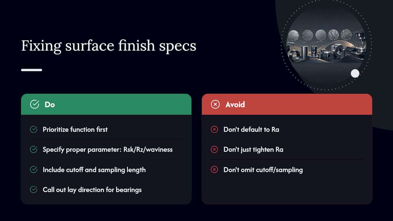
The conventional advice, “specify tighter for critical parts,” ignores the fact that Ra alone can’t guarantee sealing or wear performance regardless of how low the number goes. If the surface function depends on peak geometry, the fix is a better parameter choice (Rsk, Rz, or a waviness limit), not a smaller Ra target. Cutoff and sampling length deserve equal weight to the numeric callout. A spec without a cutoff is not really a spec. It’s a guess that happens to have units attached.
Prioritize function first, parameter second, and number last. That order gets you a part that works, not just one that measures well on paper.
— Andrew
Sources
- Surface Texture (Surface Roughness, Waviness, and Lay) – ASME
- ISO 4287:1997 — Surface texture: Profile method
- Surface Roughness Conversion Chart Tables — Engineers Edge