

A single missed dimension on a flight-critical component can ground an entire fleet, trigger a costly recall, or worse. In aerospace and defense, the margin for error is not just tight, it is essentially zero. Quality assurance managers at OEMs carry the weight of that reality every day, balancing speed-to-delivery with the absolute requirement for part integrity. This guide walks through every stage of a rigorous verification program, from preparation and standards alignment through advanced metrology, measurement validation, and documentation, so your team can catch defects before they become disasters.
Table of Contents
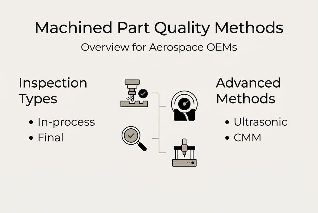
- Assessing quality requirements and preparation steps
- Inspection methods: In-process and final verification
- Advanced techniques for high-complexity and tight-tolerance parts
- Verifying measurement accuracy and troubleshooting common errors
- Documenting and closing the loop on quality outcomes
- What most quality guides miss: The integration gap and digital readiness
- Take your quality program further with Machining Technologies
- Frequently asked questions
Key Takeaways
| Point | Details |
|---|---|
| Prioritize standards compliance | Align your process with AS9102, NADCAP, and other relevant aerospace standards for uncompromising quality. |
| Apply multi-stage verification | Use in-process and final inspections to detect and correct issues before parts reach users or the field. |
| Adopt advanced NDT methods | Leverage ultrasonic, X-ray, and Barkhausen Noise analysis for subsurface and stress-related defect detection. |
| Validate measurement setup | Correct datum simulation and fixturing are essential to avoid costly GD&T and CMM errors. |
| Document and close the loop | Maintain comprehensive inspection records and feedback systems to drive ongoing quality improvement. |
Assessing quality requirements and preparation steps
Before a single part hits the inspection table, your team needs a clear picture of what “acceptable” actually means for that component. That starts with the governing standards. AS9100 sets the quality management framework for the aerospace sector, while AS9102 requires 100% first article inspection in aerospace, a fundamentally different approach from automotive’s sampling-based PPAP process. NADCAP adds process-specific accreditation requirements for special processes like heat treating and NDT. Knowing which standards apply to each part family is step one.
Next, pull the full documentation package: engineering drawings, GD&T callouts, material certifications, and any customer-specific quality plans. Review every machining tolerances for precision requirement against your production capability data. Identify critical dimensions, safety-critical features, and any tolerance stack-ups that could interact across an assembly.
| Standard | Scope | Inspection requirement | Key focus |
|---|---|---|---|
| AS9100 | QMS framework | Process and system audits | Risk management, traceability |
| AS9102 | First article inspection | 100% dimensional verification | Design conformance |
| NADCAP | Special processes | Process audits and testing | Heat treat, NDT, coatings |
| PPAP | Automotive supplier approval | Sampling-based | Process capability |
Define your inspection checkpoints before production begins. Which dimensions get checked at setup? Which get verified in-process? Which require final CMM measurement? Mapping this out prevents gaps and avoids the scramble of discovering a critical feature was never verified until the part is already in shipping.
Following aerospace machining best practices also means reviewing your manufacturing quality control approach against current industry benchmarks regularly.
Pro Tip: When drawings contain ambiguous datum references or conflicting GD&T callouts, resolve them with the engineering team before inspection begins, not after a nonconformance report surfaces mid-production.
Inspection methods: In-process and final verification
Once requirements are clear, it is time to select and apply the right inspection methods for each stage of production. The distinction between in-process and final inspection is not just procedural. It is strategic. In-process inspection catches drift before it compounds. Final inspection confirms conformance. Relying only on final inspection is expensive and reactive.
Here is a practical workflow for structuring your inspection program:
- Setup verification: Confirm fixturing, tooling offsets, and datum alignment before the first cut. Use a reference part or setup piece to validate the program.
- First-piece inspection: Measure all critical dimensions on the first production part. Compare against nominal and flag any features approaching tolerance limits.
- In-process monitoring: Deploy probing systems or gauging at defined intervals. Use statistical process control (SPC) to track Cp and Cpk values in real time.
- Escalation triggers: Define the Cpk threshold (commonly 1.33 for aerospace) at which the process must stop for review.
- Final inspection: Perform 100% verification of all critical dimensions on flight-critical parts using calibrated CMMs and appropriate gauging.
In-process inspection with probes and SPC reduces reject rates through real-time process control, which is why leading aerospace suppliers treat SPC not as a reporting tool but as an active intervention system. Connecting your precision parts manufacturing quality data to SPC dashboards closes the feedback loop faster than manual review ever could.
Safety note: For flight-critical dimensions such as bore diameters on turbine disks or thread engagement on structural fasteners, 100% verification is non-negotiable. Sampling is not an acceptable substitute when failure modes include catastrophic structural loss.
Pro Tip: Use production quality monitoring data to set dynamic control limits rather than relying solely on print tolerances. A feature consistently running at 80% of tolerance is a process warning, even if it is technically in spec.
Advanced techniques for high-complexity and tight-tolerance parts
For parts with the highest complexity or requiring subsurface integrity, advanced inspection moves from best practice to necessity. Standard CMM measurement and surface gauging simply cannot detect every failure mode in components like turbine blades, landing gear forgings, or high-cycle fatigue gears.
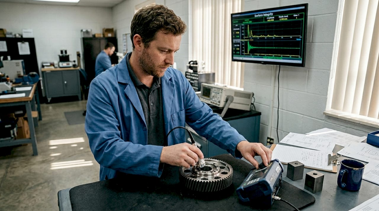
NDT methods including ultrasonic, X-ray, and Barkhausen Noise Analysis are essential for detecting subsurface and surface integrity issues that visual or dimensional inspection will never catch. For turbine blades with complex internal cooling channels, adaptive ultrasonic testing with digital mapping provides conformance data that traditional UT simply cannot match.
For aerospace gears, the shift is equally significant. Barkhausen Noise Analysis is emerging as a preferred alternative to Nital etching because it is non-destructive, faster, and provides quantitative surface stress data rather than a pass/fail visual result.
| Method | Application | Detects | Limitation |
|---|---|---|---|
| Ultrasonic testing (UT) | Forgings, castings, welds | Subsurface voids, cracks | Geometry-dependent |
| X-ray / CT scanning | Complex internal features | Internal defects, porosity | Cost, throughput |
| Barkhausen Noise (BNA) | Ground/hardened surfaces | Grinding burns, residual stress | Ferromagnetic parts only |
| Multi-sensor CMM | Complex geometry | Form, position, surface finish | Setup time |
When should you escalate to advanced techniques? Consider these triggers:
- Part has safety-critical subsurface features (e.g., pressure vessels, rotating components)
- Surface finish requirements are below Ra 0.4 µm with grinding burn risk
- Geometry prevents full contact CMM access
- Customer or regulatory specification explicitly requires NDT
- Prior nonconformances involved undetected subsurface defects
Thermal growth is a common pitfall with tight-tolerance parts. Measuring a part at shop temperature immediately after machining can produce readings that differ from a temperature-stabilized measurement by several microns. For complex manufacturing strategies involving titanium or Inconel, always allow thermal stabilization before final CMM runs. Consult your machinability materials guide for material-specific thermal expansion coefficients.
Verifying measurement accuracy and troubleshooting common errors
Even with robust inspection, errors can arise. Here is how to ensure accuracy and resolve discrepancies before they become nonconformances.
Measurement errors in GD&T most commonly stem from incorrect datum setup, requiring precise fixturing and CMM programming to avoid false rejects or, more dangerously, false accepts. The most common errors QA teams encounter include:
- Incorrect datum reference frame simulation in CMM software
- Thermal expansion not compensated for in measurement environment
- Probe qualification errors leading to systematic offset
- Fixturing that introduces part deflection during measurement
- Misapplication of material condition modifiers (MMC vs. RFS) in GD&T evaluation
When a result falls out of tolerance, follow this escalation sequence:
- Repeat the measurement using the same method to rule out operator error.
- Use an alternative method (e.g., optical comparator vs. CMM) to confirm the reading.
- Check the CMM program against the drawing, specifically datum simulation and tolerance evaluation settings.
- Inspect the fixturing for part movement or deflection.
- Escalate to engineering if two independent methods confirm an out-of-tolerance condition.
- Initiate a nonconformance report and disposition the part per your quality plan.
Review your machining tolerances best practices to confirm that tolerance callouts on the drawing are achievable with your current process capability before production begins. Understanding why tight tolerances matter in aerospace helps frame these conversations with both engineering and production teams.
Pro Tip: Always validate your CMM program on a known artifact or reference part before running a production inspection batch. A single incorrect alignment offset can invalidate an entire lot’s worth of data.
Documenting and closing the loop on quality outcomes
With verification complete, ensuring robust documentation makes all your effort count and builds a foundation for continuous improvement. Documentation is not just a compliance obligation. It is your early warning system.
Core documentation requirements for aerospace and defense include:
- First Article Inspection (FAI) reports per AS9102, covering all drawing requirements
- Material and process certifications traceable to heat/lot numbers
- SPC data records showing process capability over time
- Nonconformance reports (NCRs) with root cause and corrective action
- Calibration records for all measurement equipment used
SPC trend monitoring for root cause analysis, test records for compliance audit trails, and 100% verification for aerospace are the practices that separate suppliers who pass audits from those who drive them.
| Document type | Purpose | Compliance role |
|---|---|---|
| FAI report | Confirms design conformance at launch | AS9102, customer approval |
| SPC data | Tracks process stability over time | Ongoing process control |
| NCR with RCA | Documents defects and corrective actions | CAPA, audit evidence |
| Calibration records | Validates measurement equipment | ISO 17025, AS9100 |
A real-world example: one aerospace supplier reduced their reject rate by 34% over two production quarters after implementing a structured root cause analysis process tied directly to SPC trend data. The fix was not a new machine or tool. It was closing the feedback loop between inspection data and the production floor. Your real-time quality monitoring capability is only as valuable as the action it drives. Learn more about why monitoring manufacturing quality is central to operational excellence.
What most quality guides miss: The integration gap and digital readiness
Most quality guides stop at the procedural level, listing methods and tools without addressing the deeper structural problem: disconnected data. In many aerospace and defense operations, CMM outputs live in one system, SPC dashboards in another, and manual inspection logs in a binder on the shop floor. That fragmentation is where defects hide.
When data cannot flow between systems automatically, patterns go undetected. A feature that drifts toward its tolerance limit across three consecutive lots may trigger no alarm because no single system sees all three data points together. The result is a preventable nonconformance that becomes a field issue or a regulatory finding.
Digital traceability is not a future-state aspiration. It is a current competitive requirement. OEMs that integrate their integrated quality monitoring platforms with production scheduling, CMM software, and SPC tools respond to process drift in hours, not days. They also walk into audits with complete, searchable records rather than scrambling to reconstruct a paper trail.
The shift toward Barkhausen Noise over Nital etching and adaptive UT with digital mapping reflects the same principle: digital methods generate structured, traceable data that feeds back into process improvement. Managers who prioritize system integration over individual tool capabilities will outperform those who do not, regardless of how sophisticated their individual inspection equipment is.
Take your quality program further with Machining Technologies
If you are managing quality verification for aerospace or defense components, the gap between a good process and a great one often comes down to your machining partner’s built-in quality infrastructure.

At Machining Technologies LLC, we have been producing precision components for regulated industries since 1985, with over 20 million parts manufactured annually from our 70,000 square foot facility in Webster, Massachusetts. Our faster contract machining capabilities mean you do not have to trade speed for compliance. Explore our precision manufacturing solutions or review our aerospace best practices to see how we support OEM quality programs from first article through full-rate production. Contact us to discuss a workflow audit or pilot project.
Frequently asked questions
What is the most critical inspection method for aerospace machined parts?
For safety-critical parts, 100% final inspection of all critical dimensions using calibrated CMMs and NDT is essential to meeting both compliance and performance requirements. No sampling strategy is an acceptable substitute for flight-critical features.
How can in-process inspections improve production yield?
SPC and in-process probe inspections catch process drift before it produces out-of-tolerance parts, which directly reduces reject rates and improves overall process capability scores.
What are common causes of measurement errors in aerospace part verification?
Incorrect datum simulation and thermal growth compensation errors are the most frequent root causes, along with improper CMM fixturing that introduces part deflection during measurement.
How do AS9102 and PPAP standards differ in part verification?
AS9102 requires 100% first article and final inspection for aerospace components, while PPAP in automotive typically relies on sampling plans and process capability audits rather than 100% dimensional verification.
Recommended
- Aerospace machining best practices for precision | Machining Technologies
- Aerospace machining: precision processes and standards | Machining Technologies
- Precision Parts Manufacturing: Maximizing Quality and Throughput | Machining Technologies
- Why tight tolerances matter for aerospace machining | Machining Technologies