

When aerospace engineers design a turbine blade that spins at 10,000 RPM in 2,000°F exhaust gases, a dimensional error of just 0.0002 inches can trigger catastrophic failure. Yet many procurement teams still view tolerances as mere specification lines rather than the foundation of component safety and mission success. Understanding how micron-level precision directly impacts fatigue life, assembly reliability, and lifecycle cost separates successful aerospace programs from expensive redesigns.
Table of Contents
- The Critical Role Of Tight Tolerances In Aerospace Components
- Precision Machining Requirements And Standards In Aerospace
- Challenges Impacting Tight Tolerance Manufacturing: Residual Stresses And Surface Flaws
- Design For Manufacturability: Balancing Tight Tolerances And Cost
- Explore Precision Machining Solutions Tailored For Aerospace
- Frequently Asked Questions
Key takeaways
| Point | Details |
|---|---|
| Tight tolerances ensure precise fit and optimal component performance | Dimensional accuracy governs assembly fit, load path predictability, and aerodynamic efficiency in flight-critical parts. |
| Machining processes achieve micron-level accuracy to meet functional needs | Positional accuracy within ±5 µm and surface finishes below 0.4 µm Ra represent standard aerospace requirements. |
| Proper tolerance application balances safety with cost and manufacturability | Strategic tolerance design prevents costly rework while maintaining the precision necessary for safety and reliability. |
| Residual stresses and surface anomalies critically affect fatigue life | Manufacturing-induced stresses and handling damage initiate crack propagation that reduces component lifespan. |
| Design for manufacturability optimizes tolerance strategy | Applying tightest tolerances only where functionally necessary reduces cost and improves production throughput. |
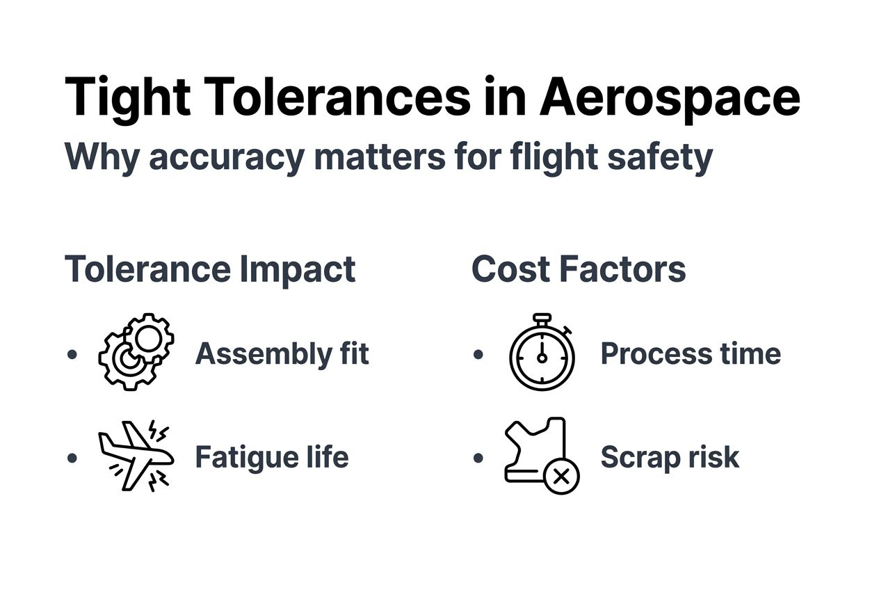
The critical role of tight tolerances in aerospace components
Tolerance specifications govern far more than dimensional variation. They directly control assembly fit, mechanical load distribution, and structural integrity across every aerospace system. In turbine assemblies, blade tip clearances measured in thousandths of an inch determine engine efficiency and prevent catastrophic rubs. Landing gear components require precise alignment to distribute impact loads during touchdown, where misalignment creates stress concentrations that accelerate fatigue crack initiation.
Precise assembly fit, predictable load paths, and optimal aerodynamic performance depend entirely on manufacturing dimensional control. Thermal cycling during flight operations imposes additional demands. Engine components experience temperature swings exceeding 1,500°F between ground idle and takeoff power. Materials expand and contract, making dimensional stability under thermal stress essential for maintaining seal integrity and bearing preloads throughout the operational envelope.
Precision manufacturing directly reduces assembly time and rework costs. When mating surfaces meet specified tolerances consistently, technicians eliminate manual fitting operations that consume production hours. Flight-critical mechanisms in life support systems, flight controls, and fuel delivery require custom machining for aerospace and defense applications where micron-level precision ensures reliable operation across thousands of flight cycles.
“Every micron of dimensional error compounds through assembly stackups, potentially causing interference fits to bind or clearance fits to rattle loose under vibration.”
Key tolerance impacts include:
- Assembly fit quality determining manual fitting time and labor costs
- Load path predictability affecting stress distribution and structural margins
- Seal effectiveness controlling fluid leakage in hydraulic and fuel systems
- Bearing preload consistency influencing rotational friction and wear rates
- Aerodynamic surface continuity impacting drag coefficients and fuel efficiency
Lifecycle costs reflect tolerance decisions made during initial design. Loose tolerances may reduce initial manufacturing expense but create field maintenance burdens when components wear unevenly or require frequent adjustment. Conversely, unnecessarily tight tolerances drive up production costs without corresponding performance benefits. Strategic tolerance application requires understanding which dimensions critically affect function versus those serving primarily as reference features.
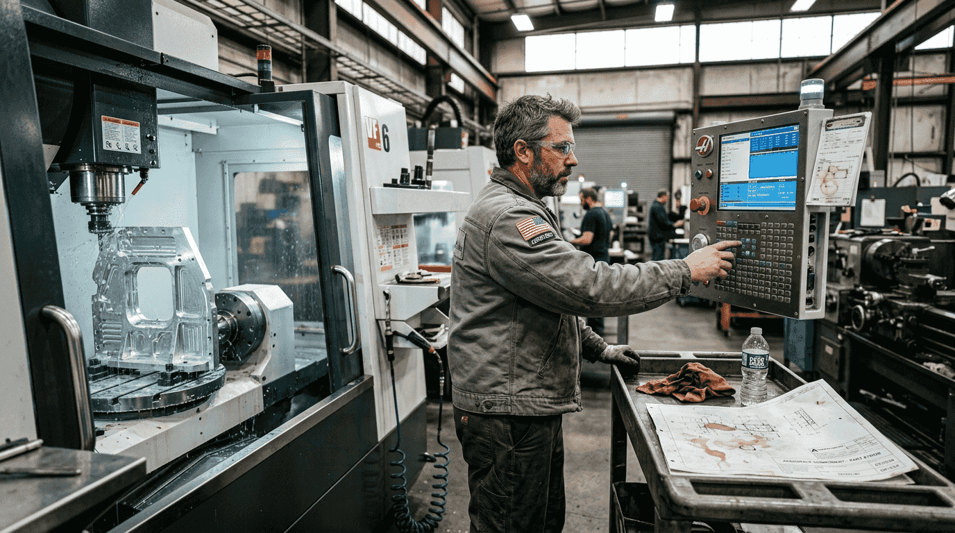
Precision machining requirements and standards in aerospace
Aerospace machining operations routinely achieve positional accuracy within ±5 µm and surface finishes below 0.4 µm Ra for flight-critical components. These specifications represent functional requirements rather than arbitrary standards. Turbine disk bolt holes require precise positional accuracy to distribute clamping loads evenly across dozens of fasteners. Position errors create uneven loading that initiates fretting fatigue at hole edges.
Roundness tolerances below 10 µm ensure bearing races provide uniform load distribution across rolling elements. Out-of-round conditions create point loading that accelerates surface spalling and premature bearing failure. Flatness specifications control seal surface mating, where deviations allowing fluid bypass reduce system efficiency and reliability. Surface finish requirements vary dramatically with function. Bearing journals require mirror finishes below 0.2 µm Ra to minimize friction and wear. Hydraulic sealing surfaces demand similar smoothness to prevent fluid weepage. Structural interfaces tolerate coarser finishes where friction rather than smoothness provides the desired joint characteristic.
Pro Tip: Invest in thermal stability controls for your machining environment. Temperature variations of just 2°F can cause dimensional shifts exceeding tight tolerances in aluminum components during multi-hour machining cycles.
| Tolerance Parameter | Typical Requirement | Application Example | Measurement Method |
|---|---|---|---|
| Positional Accuracy | ±0.0002 in (±5 µm) | Turbine disk bolt holes | CMM touch probe |
| Roundness | 0.0004 in (10 µm) | Bearing races | Form measurement |
| Flatness | 0.0002 in (5 µm) | Seal mating surfaces | Surface plate indicator |
| Surface Finish | 16 µin Ra (0.4 µm) | Hydraulic cylinder bores | Profilometer |
| Parallelism | 0.0001 in (2.5 µm) | Mounting pad faces | Height gauge comparison |
Repeatability across production batches determines whether tolerance specifications translate into consistent component performance. Single-piece accuracy means little if the next hundred parts drift outside specification limits. Statistical process control monitors dimensional trends, allowing corrective action before parts exceed tolerance boundaries. Temperature-controlled machining environments maintain dimensional stability during cutting operations. Modern aerospace facilities regulate ambient temperature within ±1°F and use thermal compensation in CNC controls to adjust for remaining variations.
In-process measurement catches tolerance deviations before completing expensive operations. Probing cycles during machining verify critical features, preventing wasted effort on parts already outside specification. This integration of machining trends for faster lead times and longer tool life with precision control defines contemporary aerospace manufacturing capability.
Challenges impacting tight tolerance manufacturing: residual stresses and surface flaws
Residual stresses represent locked-in forces within machined parts that distort dimensions as material removal progresses. These internal stresses arise from non-uniform cooling after casting, forging-induced plastic deformation, and thermal gradients during welding or heat treatment. When machining removes material containing residual stress, the remaining structure redistributes loads to achieve equilibrium, causing dimensional shifts that exceed tight tolerances.
Boeing reported $290M attributed to residual stress-induced distortions across aerospace component manufacturing. Titanium alloy structures prove particularly susceptible because the material’s low thermal conductivity creates steep thermal gradients during welding and heat treatment. Standard stress relief techniques like thermal soaking often prove inadequate for complex geometries where through-thickness temperature uniformity becomes difficult to achieve.
Mitigation strategies include:
- Rough machining to near-net shape followed by stress relief before finish operations
- Symmetrical material removal patterns that balance residual stress redistribution
- Vibration stress relief using controlled resonant frequencies to yield high-stress regions
- Shot peening to induce beneficial compressive surface stresses countering tensile residuals
- Cryogenic treatment cycles promoting microstructural stability in tool steels and titanium alloys
Surface anomalies from handling damage initiate fatigue cracks that propagate under cyclic loading, reducing component service life below design predictions. Scratches, dents, and tool marks concentrate stress at the surface where alternating loads first cause plastic deformation. Nickel superalloy turbine components operating at elevated temperatures show particular sensitivity to surface damage crack propagation because high-temperature oxidation accelerates crack growth rates.
New fracture mechanics models account for microscopic crack initiation and short-crack growth stages that earlier theories ignored. These refined predictions show that prior fatigue life estimates were overly conservative for pristine surfaces but unconservative when handling damage existed. Understanding how component geometry and stress state interact with surface condition allows more accurate fatigue life predictions during design validation.
“A 0.005-inch deep scratch in a turbine blade airfoil can reduce high-cycle fatigue life by 40 percent compared to an undamaged surface under identical operating conditions.”
Surface protection during manufacturing and assembly becomes critical. Protective coatings, careful handling procedures, and visual inspection protocols prevent damage that undermines the precision machining investment. Specifying appropriate machining tolerances for precision applications requires understanding both dimensional control and surface integrity requirements that jointly determine component reliability.
Design for manufacturability: balancing tight tolerances and cost
Manufacturing cost escalates exponentially as tolerance requirements tighten beyond standard machine capabilities. A feature machined to ±0.005 inches represents routine production work. Tightening that specification to ±0.0005 inches may double machining time through additional finishing passes and in-process inspection. Further tightening to ±0.00005 inches could require specialized grinding or lapping operations that increase cost tenfold.
Designers should apply tight tolerances only where functionally necessary for assembly fit, load distribution, or operational performance. Non-critical dimensions tolerated to standard machine capability reduce manufacturing burden without compromising component function. Tolerance stackup analysis identifies which individual dimensions require tight control to achieve assembly-level performance requirements.
Pro Tip: Review tolerance specifications with manufacturing engineers during design reviews. Features that appear reasonable on drawings may require impractical machining sequences or specialized fixturing that doubles production costs.
| Tolerance Class | Positional Tolerance | Relative Cost | Typical Process | Lead Time Impact |
|---|---|---|---|---|
| Standard | ±0.005 in (±125 µm) | 1.0x | CNC milling/turning | Baseline |
| Precision | ±0.001 in (±25 µm) | 2.5x | CNC + finish grinding | +30% |
| High Precision | ±0.0002 in (±5 µm) | 6.0x | Grinding + honing | +60% |
| Ultra Precision | ±0.00005 in (±1.25 µm) | 15.0x | Diamond turning/lapping | +120% |
Strategic tolerance planning prevents costly rework cycles. When designers specify realistic tolerances aligned with manufacturing capabilities, production runs achieve first-article approval without dimensional adjustments. Overly tight tolerances often result in rejected first articles, requiring design reviews that delay production schedules and increase program costs.
Comparison of manufacturing approaches reveals optimization opportunities. For bearing bore diameters requiring ±0.0002-inch tolerance, reaming after boring may achieve the specification more economically than fine boring alone. For thin-wall features prone to deflection during machining, rough machining followed by stress relief and finish operations produces better dimensional results than attempting to hold tolerances in a single setup.
Manufacturers should budget additional process development time for parts with multiple ultra-tight tolerances. The first production run typically reveals tool deflection issues, thermal drift problems, or fixturing inadequacies requiring corrective action. This learning curve proves normal for challenging work but requires schedule accommodation. Understanding complex part manufacturing strategies helps engineering teams set realistic expectations for precision component development timelines.
Explore precision machining solutions tailored for aerospace
Aerospace and defense programs demand manufacturing partners who understand the critical relationship between tight tolerances and component reliability. Machining Technologies brings decades of experience managing precision requirements for flight-critical applications where dimensional control directly impacts safety and performance.
Our advanced machining capabilities handle the tightest tolerance specifications while maintaining production efficiency. From prototype development through full-scale production runs, we provide comprehensive support for complex part manufacturing strategies that optimize quality and cost. Our climate-controlled facility and in-process measurement systems ensure dimensional stability throughout multi-operation manufacturing sequences.
Explore our full range of precision machining services designed specifically for aerospace and defense applications. Whether you need turbine components, structural assemblies, or hydraulic system parts, our team delivers the precision parts manufacturing quality your programs require. Contact us today to discuss your tolerance requirements and discover how strategic manufacturing partnerships reduce lead times while maintaining the dimensional control essential for aerospace success.
Frequently asked questions
What are machining tolerances and why do they matter in aerospace?
Machining tolerances define the permissible dimensional variation from nominal specifications, ensuring components achieve proper fit, function, and safety margins. In aerospace applications, tolerances govern assembly interchangeability, load distribution predictability, and operational reliability across flight-critical systems. Tight tolerance control prevents interference fits from binding and clearance fits from developing excessive play under vibration and thermal cycling.
How do residual stresses affect tight tolerance manufacturing?
Residual stresses cause dimensional distortions as machining removes material, making it difficult to maintain tight tolerances through completion of operations. These locked-in forces can shift dimensions beyond specification limits even after parts initially measured correctly. Boeing documented hundreds of millions in costs attributed to residual stress distortions, demonstrating the scale of this manufacturing challenge. Effective mitigation requires stress relief heat treatments, symmetrical material removal strategies, and sometimes specialized techniques like vibration stress relief beyond standard thermal processing.
What strategies help balance tight tolerances with cost?
Apply tight tolerances only where functional requirements demand precision, allowing standard tolerances elsewhere to reduce manufacturing complexity. Design for manufacturability principles help engineering teams specify realistic tolerances aligned with process capabilities, preventing costly rework cycles. Tolerance stackup analysis identifies critical dimensions requiring tight control versus reference features where looser tolerances suffice. Manufacturing partners should participate in design reviews to flag tolerance specifications that may trigger expensive specialized operations without corresponding performance benefits.
How do surface anomalies impact component fatigue life?
Surface scratches, dents, and tool marks concentrate stress that initiates fatigue cracks under cyclic loading, significantly reducing component service life. Research on nickel superalloys shows that handling damage can reduce high-cycle fatigue life by 40 percent compared to pristine surfaces. New fracture mechanics models accounting for short-crack behavior provide more accurate predictions than earlier theories. Protective handling procedures, visual inspection protocols, and surface treatments become essential for maintaining the reliability that precision machining investments are designed to deliver.
Recommended
- Why choose custom machining for aerospace and defense | Machining Technologies
- How to specify machining tolerances for precision | Machining Technologies
- Firearm parts machining: ±0.001″ tolerance ensures reliability | Machining Technologies
- Machining Trends 2026: 40% Faster Lead Times + 50% Tool Life | Machining Technologies