

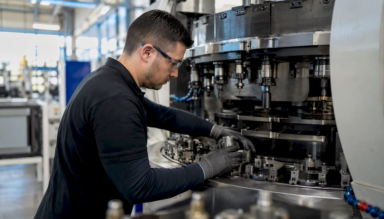
Rotary transfer machining is a multi-station, index-driven production method that completes most or all machining on a part in a single chucking. The decision rule is straightforward: use it when you need sustained annual volumes of 100,000 parts or more, tight relational tolerances across multiple features, and the lowest achievable per-part cycle time on a stable program. Platforms like Hydromat have made this technology the backbone of high-volume precision production in automotive, hydraulic, medical, and firearms manufacturing.
Before you read further, here is the quick scan:
Why it wins:
- Single-chucking accuracy eliminates setup-to-setup dimensional variation
- Simultaneous station operations compress cycle time dramatically
- Lights-out and robotic automation are native to the architecture
- Per-part cost drops steeply once tooling is amortized
Where it struggles:
- High upfront tooling and fixturing investment
- Long lead times to set up and qualify a new program
- Low flexibility for frequent part changeovers
- Skilled technicians take 6–12 months to develop fully
Key Takeaways
Rotary transfer machining delivers the lowest per-part cost for high-volume precision programs when single-chucking accuracy, simultaneous station operations, and lights-out automation are matched to a stable, long-running part family.
| Point | Details |
|---|---|
| Volume threshold | Programs below 100,000 annual units rarely justify the tooling investment; above that, per-part economics favor rotary transfer. |
| Single-chucking advantage | Completing all operations in one fixture eliminates setup-to-setup dimensional variation on relational tolerances. |
| Technician development | Plan 6–12 months to develop a qualified setup technician; cross-train a second from day one. |
| DFM before tooling | A DFM review before fixture design is ordered can reduce station count and cut tooling cost by 15% or more. |
| Machiningtechllc | Operates Hydromat cells producing over 20 million parts annually; offers feasibility estimates and pilot runs for qualifying programs. |
Table of Contents
- How does rotary transfer machining work?
- What machine types and architectures are available?
- What are the real advantages and limitations?
- Which industries and part families benefit most?
- From planning to run: how do you implement a rotary transfer program?
- Rotary transfer vs. CNC turning and Swiss-style machines: which do you choose?
- Design for rotary transfer: what geometry choices actually matter?
- What does rotary transfer actually cost, and when does it break even?
- What materials and cycle times can you realistically expect?
- What lead times and ramp-up steps should you plan for?
- How do you keep a rotary transfer machine running?
- Machining Technologies: a real high-volume program in practice
- When Machining Technologies recommends rotary transfer
- Machiningtechllc’s Hydromat and contract machining services
- Sources
How does rotary transfer machining work?
The machine centers on an indexing table, typically a horizontal carousel or vertical Ferris-wheel arrangement, fitted with pallet or collet fixtures at each station position. A raw blank or barstock is loaded at the first position; the table indexes one step, and every occupied station begins its operation simultaneously. By the time the table completes a full revolution, a finished part exits at the unload position.
Core components:
- Indexing table: rotates intermittently or continuously, carrying workpieces from station to station
- Pallet/collet fixtures: hold the part in a fixed, repeatable orientation throughout the entire cycle
- Independent machining stations: each spindle unit has its own feed rate, speed, and stroke, so a drilling station and a threading station run concurrently without waiting on each other
- Inverters/part flippers: allow two-sided machining without a second chucking operation
- In-cycle gauging: probes or air gauges check critical dimensions mid-cycle and feed offsets back to the control
- Loaders/unloaders: bar feeders, vibratory bowl feeders, or robotic arms that keep the machine running without an operator standing at the door
Cycle flow, step by step:
- Load: a blank or cut-off piece is placed into the fixture at the load station
- Saw-off or feed: on barstock machines, the bar advances and a cut-off station separates the blank
- Index: the table advances one position; all stations engage simultaneously
- Sequential station operations: drilling, turning, milling, tapping, and broaching happen in parallel across occupied stations
- In-cycle inspection: a gauging station measures a critical feature and adjusts tool offsets if needed
- Invert (if required): a flipper station repositions the part for backside operations
- Unload: the finished part exits, often onto a conveyor or into a parts catcher
Unlike multi-spindle screw machines where the bar rotates, many rotary transfer machines keep the workpiece stationary relative to the tool, which means each station can be configured independently without being bottlenecked by the slowest operation. That distinction is what makes station-level programming so powerful: a station running a long thread-milling pass does not slow the drill station next to it.
Modern PLC and CNC-driven machines have largely replaced legacy cam-driven units. The difference matters for setup: cam-driven machines require physical cam changes for new programs, while CNC-driven stations accept parameter changes at the control. Intermittent indexing is the most common arrangement, where the table dwells while stations cut, then advances. Continuous indexing exists on some high-speed platforms but is less common for complex, multi-feature parts.
What machine types and architectures are available?
Horizontal vs. vertical arrangements
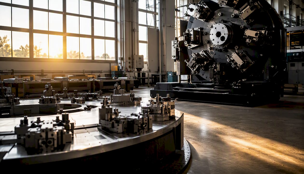
Horizontal (carousel) machines orient the indexing table in a horizontal plane, with machining units arranged radially around the perimeter. This layout handles barstock feed naturally and suits turned, drilled, and threaded parts with features accessed from the side or end. Vertical (Ferris-wheel) arrangements index the table in a vertical plane, which works well for parts requiring top-and-bottom access or where gravity-assisted chip evacuation matters.
Hydromat-style platforms and modular CNC hybrids
Hydromat systems represent the most widely recognized rotary transfer platform in North American contract manufacturing. Their defining characteristic is modularity: machining units are plug-and-play, so a shop can configure a machine with drilling, milling, turning, and tapping stations in whatever sequence the part demands. Machines can run up to 16 independently automated stations in standard configurations, with some platforms supporting 30 or more. Each unit operates with its own speed and stroke, and CNC retrofit kits allow older Hydromat frames to accept modern servo-driven heads.
Key architecture options:
- Legacy cam-driven transfer machines: low per-cycle cost once dialed in, but inflexible and increasingly hard to source parts for
- PLC/CNC-driven rotary transfer: reprogrammable stations, faster changeover than cam-driven, still slower than a machining center
- Modular CNC hybrid platforms: mix of fixed and flexible stations; support medical, hydraulic, and connector families where variety within a part family is common
- Refurbished platforms: a cost-effective entry point; industry case narratives confirm refurbished Hydromat frames remain viable for cost-conscious operations running stable programs
Station counts range from 8 on compact machines to 30-plus on large-frame platforms. More stations mean more operations per cycle, but they also mean more tooling to manage and a longer setup window.
What are the real advantages and limitations?
Advantages:
- Relational tolerance accuracy: because the part never leaves the fixture between operations, hole-to-hole spacing, concentricity, and perpendicularity are held to the fixture’s repeatability, not to multiple setups
- Throughput: simultaneous station operation means cycle time is roughly equal to the longest single-station operation, not the sum of all operations
- Compact floor footprint: one machine replaces a line of individual CNC cells
- Lights-out capability: robotic loading and in-cycle gauging make unattended overnight runs practical; industry case studies confirm this is a primary driver for shops running high-volume programs
- Profiled stock compatibility: extrusions and hex stock can be fed and machined without pre-turning
Limitations:
- High upfront investment: tooling, fixturing, and engineering setup for a new program can represent a significant capital commitment before the first good part ships
- Long setup lead time: a new program from DFM review to first production run commonly takes weeks to months
- Changeover inflexibility: switching between unrelated part families requires substantial retooling; this platform is not a job-shop machine
- Operator skill: shops commonly report 6–12 months to develop a technician capable of independent setup and troubleshooting
- Spare tooling inventory: each station needs its own perishable tooling stock, which adds carrying cost
Pro Tip: If one station’s operation is significantly longer than the others, split it across two adjacent stations running the same tool path in sequence. This balances cycle time across the table and can cut your bottleneck station time roughly in half without adding machine complexity.
Which industries and part families benefit most?
Rotary transfer is the natural home for parts that require many sequential operations, tight relational tolerances, and annual volumes that justify dedicated tooling. The economics work because the per-part variable cost drops sharply once the fixed tooling investment is spread across a large run.
Common industries and part types:
- Automotive: fuel system fittings, brake components, transmission valve bodies, and sensor housings
- Pneumatic and hydraulic: manifold bodies, valve spools, port fittings, and quick-connect bodies
- Electrical and electronic: connector bodies, terminal housings, and precision contacts
- Medical devices: catheter fittings, implant components, and fluid-path connectors where relational tolerances are critical
- Firearms and defense: bolt components, trigger housings, and small precision fittings where dimensional consistency across large runs is non-negotiable
- Industrial fittings: NPT-threaded bodies, compression fittings, and instrumentation connectors
Parts that fit the platform well share a few characteristics: multiple features accessed from different angles, a need for tight positional relationships between those features, and a geometry that can be fixtured repeatably in a collet or pallet. Small to medium parts, roughly the size of a thumb to a fist, are the sweet spot.
Annual production volumes for rotary transfer programs range from approximately 100,000 units to tens of millions depending on part complexity and machine configuration. A hydraulic fitting running on a 16-station Hydromat might cycle every few seconds; an automotive sensor housing with more complex features might run at a longer cycle but still produce hundreds of thousands of parts per year. For complex multi-feature parts, this throughput profile is difficult to match with any other process.
From planning to run: how do you implement a rotary transfer program?
Program planning steps
- Part review and DFM: evaluate the part drawing for features that can be combined, simplified, or repositioned to reduce station count and tooling complexity
- Station mapping and operations sequencing: assign each operation to a station, balance cycle times, and identify inversion requirements
- Fixture design: design collet or pallet fixtures for repeatable datum location; fixture accuracy directly determines relational tolerance capability
- Tooling list and spindle selection: specify cutting tools, holders, and spindle types for each station; include perishable tooling lead times in the schedule
- Blank feeding strategy: choose between barstock with in-machine cut-off, pre-cut blanks with bowl or magazine feed, or robotic blank loading
- In-cycle gauging design: identify the two or three dimensions most critical to function and design gauging stations to monitor them continuously
- Robotic loading/unloading integration: specify end-of-arm tooling, conveyor interfaces, and part-present sensors for lights-out operation
Setup, tryout, and steady-state checklist
- Run a short pilot batch to verify fixture seating and station alignment
- Measure the first articles against all drawing callouts, not just the gauged dimensions
- Conduct a capability study (Cpk) on critical features before releasing to production
- Set SPC control limits and assign response rules for out-of-control signals
- Document tool change intervals based on tool life data from the pilot run
- Schedule spare tooling replenishment before the first tool change is due, not after
- Log fixture wear indicators and set inspection intervals for collet and pallet seats
Pro Tip: Advanced workholding design is where most rotary transfer programs win or lose on tolerance. A collet that seats 0.0002" off-center on every cycle will produce a scrap rate no amount of tool adjustment can fix. Invest in precision workholding engineering before the machine arrives on the floor.
The NIST process capability framework provides useful analytical tools for structuring the ramp-up capability study, particularly for establishing measurement system adequacy before committing to production Cpk targets.
Rotary transfer vs. CNC turning and Swiss-style machines: which do you choose?
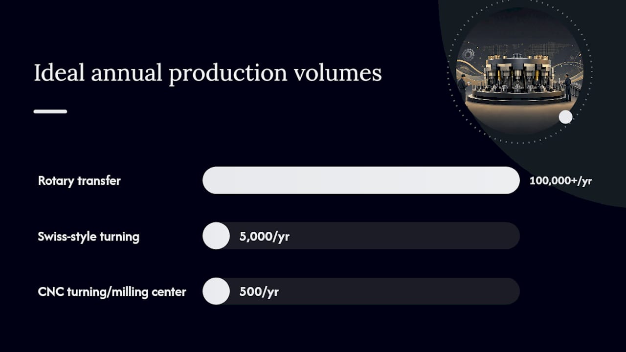
The honest answer is that rotary transfer is not a CNC replacement. It is a high-capital, dedicated platform that makes economic sense only when the program is stable, the volumes are high, and the part demands tight relational tolerances across multiple features. Industry practitioners are direct about this: the upfront investment in tooling and setup is only justified by the economies of scale that come with long, stable runs.
| Dimension | Rotary transfer | CNC turning/milling center | Swiss-style turning |
|---|---|---|---|
| Ideal production volumes | 100,000+ units/year, stable program | 500 units, mixed programs | 5,000 units, small-diameter parts |
| Upfront tooling and fixturing cost | High (dedicated fixtures, multiple station toolsets) | Low to moderate (standard tooling, soft jaws) | Moderate (guide bushing, bar prep, tooling) |
| Per-part cycle time/throughput | Very low; simultaneous stations compress cycle | Moderate; sequential operations add up | Low for small-diameter turned parts |
| Part complexity/tolerance capability | Excellent for multi-feature relational tolerances | Good for complex geometry, less repeatable across setups | Excellent for long slender parts, less suited to multi-sided features |
| Flexibility/changeover time | Low; major retooling for new part families | High; new program in hours to days | Moderate; bar change and guide bushing swap |
Decision rules in practice:
- Choose rotary transfer when annual volume exceeds 100,000 units, the part has five or more sequential operations, and relational tolerances between features are tighter than ±0.001"
- Choose a CNC machining center when volumes are below that threshold, the program is likely to change, or the part requires complex 5-axis geometry that does not fit a radial station layout
- Choose Swiss-style turning for small-diameter, long-aspect-ratio parts where bar-feed efficiency and sub-spindle capability matter more than multi-sided access
Hybrid approaches make sense more often than engineers expect. Blanking or rough turning on a Swiss machine, then finishing on a rotary transfer cell, can capture the tolerance benefits of single-chucking while keeping the Swiss machine free for other programs. This is particularly useful for medical connector families where variety within a part family is high but volumes per variant are moderate.
Design for rotary transfer: what geometry choices actually matter?
Design for rotary transfer (DFM) is where engineers can save the most money before a single tool is ordered. Poor feature placement forces extra stations; poor datum strategy forces tight tolerances onto the fixture instead of the part drawing where they belong.
Feature placement and symmetry:
- Locate features that must hold tight positional relationships to each other on the same datum axis whenever possible; this lets the fixture carry the tolerance rather than requiring a precision transfer between stations
- Avoid features that require the part to be re-fixtured mid-cycle unless an inversion station is already planned; each re-fixturing is a tolerance stack-up event
- Radially symmetric features index naturally with the table; asymmetric features may require a dedicated orientation station that consumes a station count without adding material removal
Tolerance allocation:
- Hold tight tolerances on features that are functionally critical and can be gauged in-cycle; allocate looser tolerances to features that are easy to check offline
- Relational tolerances (hole-to-hole spacing, concentricity) are the platform’s strength; use them aggressively in the design and let the fixture carry them
- Avoid specifying tighter tolerances than the function requires; every 0.0001" tightened on a non-critical feature adds tooling cost and scrap risk
Pro Tip: Prefer through-holes over blind holes wherever the function permits. Through-holes allow the drill to break out cleanly, simplify chip evacuation, and eliminate the need for a peck-drilling cycle that adds station dwell time. On a 16-station machine running millions of parts per year, a two-second dwell reduction per part is worth calculating.
- Use precision machining tolerance analysis to verify that your tolerance stack-up across stations is achievable before finalizing the fixture design
- Prefer chamfers over radii at feature intersections; chamfers are easier to produce with standard tooling and do not require a dedicated form tool
- Design for datum reuse: if the same datum surface locates the part at stations 1, 4, and 8, the fixture needs to maintain that surface’s condition throughout the cycle
What does rotary transfer actually cost, and when does it break even?
The economics of rotary transfer hinge on one trade-off: high fixed costs against very low variable costs per part. The fixed costs are real and front-loaded; the variable costs are where the platform wins.
Primary cost drivers:
- Machine CAPEX: new Hydromat-style platforms represent a substantial capital investment; refurbished machines reduce this significantly
- Fixturing and tooling: dedicated fixtures, collets, and station toolsets are program-specific; they cannot be reused on unrelated parts
- Perishable tooling: drills, taps, inserts, and form tools consumed during production; these are ongoing variable costs
- Engineering and setup hours: station mapping, fixture design, tryout, and capability studies add up before the first production part ships
- Floor space and infrastructure: coolant systems, chip conveyors, and robotic cell integration add to the total installed cost
Break-even calculation example (generic):
Assume total fixed program cost (CAPEX amortization share + fixturing + engineering) of $X. Assume per-part variable cost on rotary transfer of $V_RT, versus $V_CNC on a CNC cell. Break-even volume = $X / ($V_CNC minus $V_RT). The larger the gap between the two variable costs, the faster the break-even. On programs running millions of parts per year, break-even often occurs within the first year of production.
| Cost component | Category | ROI model allocation |
|---|---|---|
| Machine CAPEX (amortized) | Fixed | Spread over program life (years) |
| Fixture and dedicated tooling | Fixed/semi-fixed | Amortized over expected part run |
| Perishable tooling | Variable | Per-part or per-1,000-part rate |
| Engineering and setup | Fixed | One-time or per-new-program |
| Operator and maintenance labor | Variable | Per-shift or per-hour rate |
| Floor space and utilities | Fixed overhead | Allocated by machine footprint |
The Production Machining guidance on this is clear: rotary transfer is best for long-term, high-volume programs because the upfront investment only pays back at scale. If your program has a realistic end-of-life within two years and volumes are below 100,000 annually, the math rarely closes.
What materials and cycle times can you realistically expect?
Rotary transfer handles most machinable metals without issue. The platform’s strength is in materials that machine cleanly at high speeds, where tool life is predictable enough to schedule changes rather than react to breakage.
Commonly processed materials:
- Free-machining steels and alloy steels: the most common; predictable tool life and excellent surface finish
- Stainless steels: workable but harder on tooling; station dwell times increase and tool change intervals shorten
- Aluminum alloys: fast cycle times, excellent chip control with proper geometry; common in aerospace and connector applications
- Brass and copper alloys: ideal for the platform; free-machining grades run at high speeds with long tool life
- Exotic alloys (titanium, Inconel): possible but demanding; reduced speeds, shorter tool life, and more frequent in-cycle gauging checks are needed
Part size typically ranges from small connectors a few millimeters in diameter up to parts roughly the size of a fist. Larger parts are possible on large-frame machines but are less common; the platform’s economics favor smaller, high-volume parts where the cycle time advantage is most pronounced.
Annual production capacity on rotary transfer systems ranges from approximately 100,000 to tens of millions of parts depending on part complexity and station count. A simple fitting on a well-configured machine might cycle every 3–5 seconds; a complex part with inversion and multiple milled features might run at 15–20 seconds per cycle. With 16 or more stations running simultaneously, even the longer cycle times produce impressive annual throughput.
Station count directly affects throughput: more stations mean more operations per cycle, but the cycle time is still governed by the slowest station. Splitting that bottleneck station across two positions, as noted earlier, is the most reliable lever for improving output without adding a second machine.
What lead times and ramp-up steps should you plan for?
Project managers consistently underestimate the time from “we want to run this on rotary transfer” to “we are shipping production parts.” The machine is only part of the timeline.
Typical lead times:
- New machine procurement: 6–18 months depending on platform and configuration
- Refurbished machine sourcing and rebuild: 3–9 months
- Fixture and dedicated tooling design and fabrication: 8–16 weeks after part drawing is frozen
- Engineering setup and station mapping: 4–8 weeks concurrent with tooling fabrication
- Pilot run and capability study: 2–4 weeks after machine is tooled and running
Ramp-up checklist:
- Freeze the part drawing before tooling design begins; late drawing changes are expensive
- Complete a full DFM review with the machine operator and tooling engineer present
- Run a pilot batch of 500–1,000 parts and measure every critical dimension
- Conduct a Cpk study on the three to five most critical features; target Cpk ≥ 1.67 before releasing to production
- Train at least two technicians on setup and troubleshooting before the program goes live
- Document all tool change intervals, fixture inspection points, and SPC response rules in a production SOP
Integration considerations:
- Cell layout should allow robotic loading/unloading without operator interference during normal production
- Upstream blank prep (cut-off, wash, or heat treat) needs to be synchronized with machine feed rate
- Downstream conveyors and parts washers should be sized for the machine’s maximum output rate, not the average
- High-volume machining workflow planning should account for the full cell, not just the transfer machine itself
How do you keep a rotary transfer machine running?
Uptime on a rotary transfer machine is a maintenance discipline, not a luck-of-the-draw outcome. The machines are productive precisely because every station runs every cycle; that also means every station is a potential failure point.
Common wear items and failure modes:
- Spindle wear: high-cycle spindles wear bearing surfaces over time; vibration signatures change before failure becomes catastrophic
- Collet and chuck seating: worn collet seats produce inconsistent part location, which shows up as a gradual drift in relational tolerances before it becomes visible scrap
- Broken tooling: a broken tap or drill at one station can damage the fixture or the part at subsequent stations if the machine does not have in-cycle seat sensing
- Coolant contamination: tramp oil and bacterial growth in coolant degrade surface finish and accelerate tool wear; coolant management is a weekly discipline, not a quarterly one
- Indexing mechanism wear: the table’s indexing mechanism accumulates wear over millions of cycles; periodic backlash checks catch this before it affects part quality
Preventive maintenance checklist:
- Check spindle runout on a defined interval (weekly on high-cycle stations)
- Inspect collet and pallet seats for wear at every tool change
- Monitor coolant concentration and pH weekly; change on schedule, not on appearance
- Stock a minimum of two full sets of perishable tooling for each station; never run to zero
- Log all tool change events and scrap events by station to identify wear patterns early
Pro Tip: Install part-present and seat sensors at every station, not just the gauging stations. A missing part or a mis-seated blank that indexes through three stations before anyone notices can damage multiple tooling sets in one cycle. The sensor cost is trivial compared to the tooling replacement and downtime.
Shops commonly report 6–12 months to develop a technician who can independently set up and troubleshoot a rotary transfer machine. Plan for that timeline when staffing a new program, and build cross-training into the schedule from day one.
Machining Technologies: a real high-volume program in practice
Machiningtechllc has operated Hydromat rotary transfer systems from its 70,000-square-foot facility in Webster, Massachusetts since 1985. The facility produces over 20 million parts annually across its transfer machine cells, with individual programs running into the millions of parts per year on dedicated Hydromat platforms.
A representative program at Machiningtechllc illustrates the economics clearly:
- Part type: precision hydraulic fitting with six sequential operations (face, drill, bore, thread, cross-drill, chamfer)
- Station count: 12 active stations on a Hydromat platform, including one inversion station for backside operations
- Cycle time: approximately 8 seconds per part
- Annual volume: approximately 2 million parts per year on a single machine
- Scrap rate: held below 0.5% through in-cycle air gauging on bore diameter and thread depth
- Labor loading: one operator monitors two machines simultaneously during day shift; the cell runs lights-out on second and third shifts with robotic loading
Key operational lessons from this program:
- The DFM review caught two features that could be combined into one station operation, reducing the station count from 14 to 12 and cutting tooling cost by roughly 15%
- In-cycle gauging on the bore diameter paid back its installation cost within the first three months by catching tool wear drift before it produced out-of-tolerance parts
- Operator training took approximately eight months before the assigned technician could handle setup independently; a second technician was cross-trained concurrently to cover absences
At Machiningtechllc, the programs that perform best on our Hydromat cells are the ones where the engineering team invested in DFM before the first tool was ordered. The machines are capable of holding very tight relational tolerances, but only if the fixture design and datum strategy are right from the start. That front-end investment is what separates a program that runs profitably for years from one that struggles with chronic scrap.
The quality control practices built into the cell, including SPC charting on critical dimensions and automated tool offset feedback, are what allow the machine to run unattended without accumulating scrap overnight.
When Machining Technologies recommends rotary transfer
The decision to run a program on rotary transfer comes down to three questions: Is the annual volume high enough to amortize the tooling investment? Is the part stable enough that the program will run for years without major drawing changes? And does the part have enough sequential operations that the simultaneous-station advantage actually compresses cycle time meaningfully?
Since 1985, Machiningtechllc has evaluated hundreds of programs against those criteria. The answer is not always rotary transfer. For programs below 100,000 annual units, or for parts that are still evolving through design iterations, a CNC turning or milling approach is usually the right call. For programs above that threshold with stable drawings and multi-feature geometry, the economics of rotary transfer are hard to beat.
During scoping, Machiningtechllc commonly recommends a pilot run of 1,000–5,000 parts before committing to full production tooling. This surfaces fixture issues, identifies the real cycle-time bottleneck, and generates the Cpk data needed to set realistic production SPC limits. Amortization schedules are built into the program quote so the customer can see exactly when per-part cost crosses below the CNC alternative.
The facility’s precision parts manufacturing capabilities extend beyond the Hydromat cells to include CNC milling, turning, and wire EDM, which means hybrid programs, rough on one process and finish on another, are handled in-house without coordination across suppliers.
Machiningtechllc’s Hydromat and contract machining services
Machiningtechllc runs dedicated Hydromat rotary transfer cells alongside CNC milling, turning, and wire EDM in a 70,000-square-foot facility in Webster, Massachusetts. For OEMs and industrial manufacturers evaluating high-volume precision programs, the combination of in-house Hydromat capacity, DFM engineering support, and a track record of over 20 million parts per year makes Machiningtechllc a direct path from part drawing to production-ready components.
The starting point for most new programs is a feasibility estimate: send your part drawing, annual volume target, and tolerance requirements, and Machiningtechllc’s engineering team will assess process fit, estimate tooling investment, and outline an amortization schedule. For programs that qualify, a pilot run can be scoped and quoted in the same conversation.
To start an evaluation, visit the OEM contract machining page or contact the team directly with your RFI package. Include your annual volume target, part drawing or sketch, critical tolerance callouts, and preferred material. That information is enough to generate a meaningful first-pass feasibility assessment.
Sources
The following sources were used in preparing this guide and are worth reading directly for additional depth:
- Nvlpubs
- Rotary Transfer Versus Swiss for Small Precision Parts | Production Machining
- Where Rotary Transfers Fit, with Kris Fugate—EP. 144 – Today’s Machining World
- Hands-off Production: Understanding Rotary Transfer
Recommended
- Optimize high-volume machining workflow: aerospace precision | Machining Technologies
- Types of Small Parts Machining: Engineer’s Process Guide | Machining Technologies
- Advanced machining equipment: efficiency gains and ROI | Machining Technologies
- What Is Hydromat Machining? Key Advantages for U.S. OEMs | Machining Technologies