

TL;DR:
- Fixturing in machining locates, supports, and clamps workpieces to ensure consistent, accurate cuts. Poor fixturing increases scrap, tool wear, and cycle times, regardless of machine quality. Early fixture design, based on the 3-2-1 principle and staged clamping, is essential for precision and repeatability.
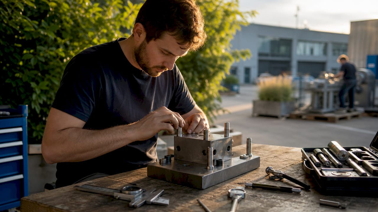
Fixturing in machining is defined as the system that locates, supports, and clamps a workpiece so every cut starts from the same controlled position. The role of fixturing in machining goes far beyond holding a part in place. It defines the physical interface between the workpiece and the machine coordinate system, which means fixture quality directly determines part quality. Poor fixturing causes increased scrap rates, out-of-tolerance parts, accelerated tool wear, and longer cycle times. Even the most advanced CNC equipment cannot compensate for an unstable workholding setup. Machiningtechllc has built its precision machining practice on this principle since 1985, producing over 20 million parts annually by treating fixture design as a core engineering discipline.
How does fixturing contribute to accuracy and repeatability in machining?
Fixturing is not peripheral to machine accuracy. Fixturing defines the accuracy system by controlling how the part meets the machine coordinate system. When the fixture is weak or inconsistent, the machine compensates for unstable starting conditions, and that compensation introduces error.
The distinction between locating and clamping is the most misunderstood concept in workholding. Locating establishes the part’s position relative to datum surfaces. Clamping holds it there against cutting forces. Confusing the two functions leads to fixtures that clamp well but locate poorly, which produces parts that look held but drift between setups.
Repeatability depends on the fixture returning the part to the same position every cycle. This is what enables interchangeable parts across a production run. A fixture that locates to within ±0.001 inches on the first setup but drifts to ±0.005 inches by the tenth setup is not a precision fixture. It is a liability.
Here is what stable fixturing actually controls in a machining environment:
- Part position: Datum surfaces on the fixture define X, Y, and Z zero for every part loaded.
- Vibration: Rigid support points prevent chatter during interrupted cuts and high-feed passes.
- Deflection: Properly placed supports stop thin walls and long features from bending under tool pressure.
- Thermal drift: A well-designed fixture minimizes the contact area that transfers heat from the part to the machine table.
Fixturing is the first link in the accuracy chain. If that link is weak, no amount of machine calibration or toolpath compensation will produce consistent results across a production run.
For complex part manufacturing, fixture accuracy is not a setup detail. It is a design requirement that must be specified before the first chip is cut.
What are the main fixturing principles and techniques used in machining?
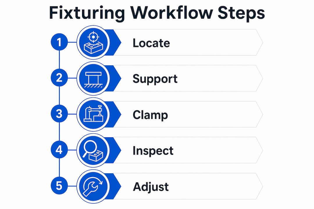
Three functions define every fixture: locate, support, and clamp. Fixture design must address all three to maintain repeatability and resist cutting forces without distorting the part. Skipping any one of them creates a gap that shows up as variation in finished parts.
The 3-2-1 locating principle
The 3-2-1 method is the standard framework for constraining a prismatic part in three-dimensional space. Three points define the primary datum plane, eliminating two rotational and one translational degree of freedom. Two points on the secondary datum eliminate one rotation and one translation. One point on the tertiary datum eliminates the final translational degree of freedom. The result is a fully constrained part with no ambiguity about its position.
Aligning design datum reference frames with fixture locating elements is the single most effective way to reduce setup complexity. When the datum surfaces used in the CAD model match the physical contact points on the fixture, the part goes in one way and one way only. When they do not match, machinists use surrogate datums, which adds setup time and introduces geometric variation.
Clamping strategy and stress relief
Clamping force must be high enough to resist cutting loads but low enough to avoid elastic deformation of the part. This balance is harder to achieve than it sounds, especially with thin-walled aerospace or defense components.
- Identify the most flexible regions of the part before designing clamp locations. Clamps placed over unsupported spans cause deflection that springs back after the cut, leaving the finished surface out of tolerance.
- Use staged clamping during roughing and finishing. High clamping force during roughing resists the aggressive cuts, then the force is relaxed before the finishing pass to release residual stress. CNC programs can execute this with M00 or M01 program stops.
- Apply clamps as close to support points as possible. This minimizes the bending moment between the clamp load and the reaction point.
- Avoid clamping across datum surfaces. Clamping force applied to a locating surface can lift the part off the datum, defeating the locating function entirely.
- Verify clamp repeatability across operators. Torque specifications on manual clamps reduce operator-to-operator variation in clamping force.
Pro Tip: Run a first-article inspection after the first setup and again after the tenth setup using the same fixture. If dimensions shift between runs, the fixture is locating inconsistently, not the machine.
Proper fixture design balances clamping force with the need to avoid part elastic deformation throughout the entire machining cycle, not just at the start.
What types of fixturing systems are typically used and their roles?
Fixture selection depends on production volume, part complexity, and how often the setup changes. The three main categories are dedicated fixtures, modular fixtures, and manual or indicating fixtures. Each has a distinct role in a production environment.
| Fixture type | Best application | Setup time | Precision | Cost |
|---|---|---|---|---|
| Dedicated | High-volume, single-part production | Minutes | Highest | High upfront |
| Modular | Medium runs, 5–50 parts | 30–90 minutes | High | Moderate, reusable |
| Manual/indicating | One-off jobs, prototypes | Hours | Variable | Low |
Dedicated fixtures are engineered for one part number and one operation. They load fast, locate precisely, and require no adjustment between cycles. For high-volume production, the upfront tooling cost is recovered quickly through cycle time savings and scrap reduction.
Modular fixturing systems are machined to tight tolerances of ±0.0005 inches, making them accurate enough for most precision work. They assemble from standardized components in 30–90 minutes instead of the weeks required to build dedicated tooling. That speed makes them the right choice for medium-volume runs of 5–50 parts where dedicated tooling cannot be justified economically.
Manual or indicating fixtures rely on the operator to locate the part by indicating off a reference surface. They work for prototype work and one-off jobs where no repeat production is expected. Their weakness is operator dependence. Two machinists using the same indicating fixture on the same part will produce different setups unless the procedure is tightly controlled.
Pro Tip: Invest in a modular fixturing system before you need it. The components pay for themselves across dozens of jobs, and the setup speed advantage compounds every time you run a new part number.
How do fixturing strategies integrate with machining center workflows?
Fixture design and machine workflow must be planned together, not sequentially. A fixture designed without considering tool access, axis travel, and spindle orientation will force compromises that cost time and accuracy on the shop floor.
Open architecture fixture designs suspend the workpiece to expose multiple faces in a single setup. This approach is fundamentally different from a standard vise, which blocks the bottom and two sides of the part. When a fixture exposes five faces, a five-axis machining center can complete the part in one setup instead of three or four. That reduction in setups directly reduces accumulated positional error.
The workflow benefits of integrated fixture planning include:
- Fewer setups per part: Each re-clamping introduces potential for positional error. Eliminating setups eliminates that error source.
- Shorter cycle times: A fixture designed around the toolpath allows the machine to run at programmed feed rates without operator interruptions for repositioning.
- Lower scrap rates: Parts that stay in one fixture from first cut to last cut do not accumulate re-referencing errors between operations.
- Better tool life: Stable fixturing reduces vibration, which is one of the primary causes of premature insert failure.
Fixturing engaged early in engineering aligns manufacturing datums and fixture locating features before the design is frozen. When fixture designers review part drawings at the concept stage, they can flag datum surfaces that will be inaccessible in the machine and suggest geometry changes that cost nothing at the design stage but would cost significant rework later.
The connection between precision parts manufacturing and fixture workflow integration is direct. Parts produced in fewer setups with stable, well-designed fixtures consistently hit tighter tolerances than parts cycled through multiple re-clampings.
Key Takeaways
Fixturing is the foundation of machining accuracy: a fixture that locates, supports, and clamps correctly determines part quality more than any other single process variable.
| Point | Details |
|---|---|
| Fixturing defines accuracy | Weak fixturing forces the machine to compensate for instability, reducing output precision. |
| 3-2-1 locating is the standard | Three datum planes fully constrain a part and eliminate positional ambiguity between setups. |
| Staged clamping prevents distortion | Reducing clamp force before finishing passes releases residual stress and protects tight tolerances. |
| Modular fixtures suit medium runs | Systems accurate to ±0.0005 inches assemble in 30–90 minutes, balancing cost and precision. |
| Early fixture design reduces variation | Aligning CAD datums with fixture locating points at the design stage eliminates surrogate datum errors. |
What I’ve learned from watching fixtures fail
The most expensive fixture mistakes I have seen did not happen on the shop floor. They happened in the engineering office, weeks before the first part was cut. A design team finalizes datum surfaces on a CAD model without consulting the machinist or the fixture designer. The part goes to production, and the machinists discover that the primary datum is a surface they cannot physically reach with the fixture in the machine. They improvise with a surrogate datum, the setup takes twice as long, and the geometric variation shows up in the first-article inspection.
The fix is not complicated. Bring fixture design into the engineering process at the concept stage, not after the drawing is released. That one change eliminates the most common source of setup inconsistency I have encountered.
The second mistake I see repeatedly is treating modular fixturing as a budget compromise. Engineers assume that dedicated tooling is always more accurate. It is not always true. A well-assembled modular fixture at ±0.0005 inches is accurate enough for the majority of precision machining work. The real advantage of modular systems is not just cost. It is the ability to respond to new part numbers without a six-week tooling lead time.
The third mistake is ignoring clamping force as a variable. Operators tighten clamps by feel, and that feel varies by person and by shift. Specifying torque values for manual clamps and using hydraulic or pneumatic clamping for high-volume work removes that variable entirely. The parts that come off a hydraulically clamped fixture at 3 AM are identical to the parts that came off at 8 AM. That consistency is what precision manufacturing actually requires.
— Andrew
Machiningtechllc’s approach to fixturing and precision machining
Machiningtechllc has applied fixture-first engineering to precision contract machining since 1985, running Hydromat systems, CNC milling, CNC turning, and wire EDM across a 70,000 square foot facility in Webster, Massachusetts.
Every project at Machiningtechllc starts with a review of datum structure and fixture strategy before programming begins. That process is what allows the facility to produce over 20 million parts annually with the repeatability that aerospace, defense, and industrial machinery customers require. If you are working on a part that demands tight tolerances and consistent output across high volumes, the contract machining services at Machiningtechllc are built for exactly that requirement. Contact the team to discuss your fixturing and machining needs directly.
FAQ
What is the primary role of a fixture in CNC machining?
A fixture locates, supports, and clamps the workpiece so it returns to the same position every cycle. This repeatability is what allows CNC machines to produce identical parts across a full production run.
How does poor fixturing affect part quality?
Poor fixturing causes increased scrap rates, out-of-tolerance dimensions, faster tool wear, and longer cycle times. Even advanced CNC machines cannot compensate for an unstable workholding setup.
What is the 3-2-1 fixturing principle?
The 3-2-1 principle uses three contact points on the primary datum, two on the secondary, and one on the tertiary to fully constrain a part in three-dimensional space. It eliminates all six degrees of freedom and removes positional ambiguity between setups.
When should modular fixturing be used instead of dedicated tooling?
Modular fixturing is the right choice for production runs of 5–50 parts where dedicated tooling cannot be justified economically. Modular systems assemble in 30–90 minutes and hold tolerances to ±0.0005 inches, making them accurate enough for most precision work.
How does fixture design affect cycle time and scrap rates?
Open architecture fixtures that expose multiple part faces allow multi-axis machines to complete parts in fewer setups. Fewer setups mean less accumulated positional error, shorter total cycle time, and lower scrap rates across the production run.
Recommended
- The Role of CAD/CAM in Machining: 2026 Guide | Machining Technologies
- Why Part Geometry Impacts Machining: 2026 Guide | Machining Technologies
- Machining Cost Estimation: A Guide for Engineers | Machining Technologies
- Optimize high-volume machining workflow: aerospace precision | Machining Technologies