

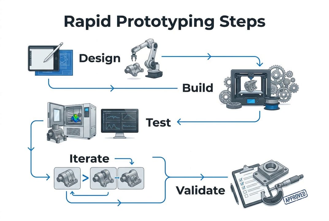
Rapid prototyping is a fast, iterative approach to building physical or digital models directly from CAD data, so you can test and validate a design before committing to full production. The goal is not to produce a perfect part. The goal is to answer a specific question about your design as quickly as possible, then adjust and repeat. That cycle, from concept to testable model and back again, is what separates rapid prototyping from traditional development, where a single prototype might take months to produce and cost a small fortune to revise.
Three principles drive the approach, as outlined in Harvard Business School’s framework for design thinking: find the fastest path to a testable experience, treat building as a form of thinking, and use materials that keep pace with your ideas rather than slowing you down for the sake of polish.
Key features of rapid prototyping at a glance:
- Converts digital CAD models into physical or functional prototypes quickly
- Supports multiple iteration cycles within a single development phase
- Uses additive methods like 3D printing, subtractive methods like CNC machining, or both
- Catches design flaws before tooling investment, reducing downstream cost and risk
- Works across industries from aerospace and defense to consumer products and medical devices
- Scales from rough concept models to high-fidelity functional prototypes
How does rapid prototyping work, step by step?
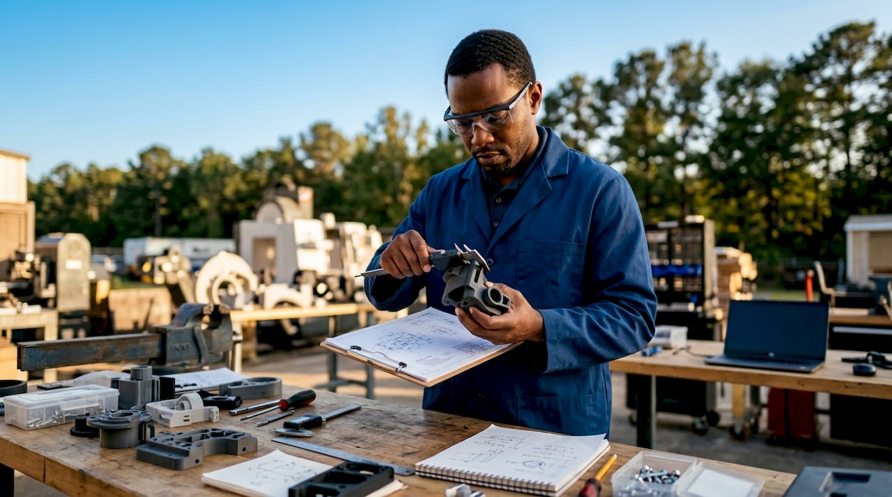
The rapid prototyping workflow follows a consistent pattern regardless of the fabrication method you choose: create a digital model, prepare the file, build the prototype, test it, and iterate. Each loop through that cycle tightens the design.
Here is how the process typically unfolds:
- CAD modeling. The design starts as a 3D solid model built in CAD software. The geometry must be a valid closed volume, meaning every surface encloses a finite interior with no gaps or overlapping faces.
- File preparation. The CAD file is exported, usually to STL format, which is the de facto standard for transferring solid geometry to fabrication equipment. For additive processes, the file is then sliced into layers. For CNC subtractive work, the CAM software generates toolpaths from the same geometry.
- Material selection. The choice of material depends on what the prototype needs to prove. A concept model for visual review needs different material properties than a functional prototype that will see mechanical stress.
- Fabrication. The machine builds or cuts the part. Additive systems deposit material layer by layer. Subtractive systems remove material from a solid block. Both can produce a testable part in hours to days rather than weeks.
- Post-processing. Depending on the method, parts may need support removal, sanding, curing, or surface finishing before they are ready to evaluate.
- Testing and iteration. The prototype gets evaluated against the specific question it was built to answer, whether that is fit, function, ergonomics, or appearance. Findings feed directly back into the CAD model, and the cycle restarts.
Common fabrication techniques used in the process:
- Fused Deposition Modeling (FDM)
- Stereolithography (SLA)
- Selective Laser Sintering (SLS)
- CNC milling and turning
- Wire EDM for tight-tolerance features
- Vacuum casting for small-batch urethane parts
Pro Tip: Resist the urge to perfect the CAD model before building. Build early, test against one specific question, and let the physical result tell you what to fix. Spending weeks refining a digital model that has never been held in a hand is one of the most common and costly prototyping mistakes.
What rapid prototyping methods are available?
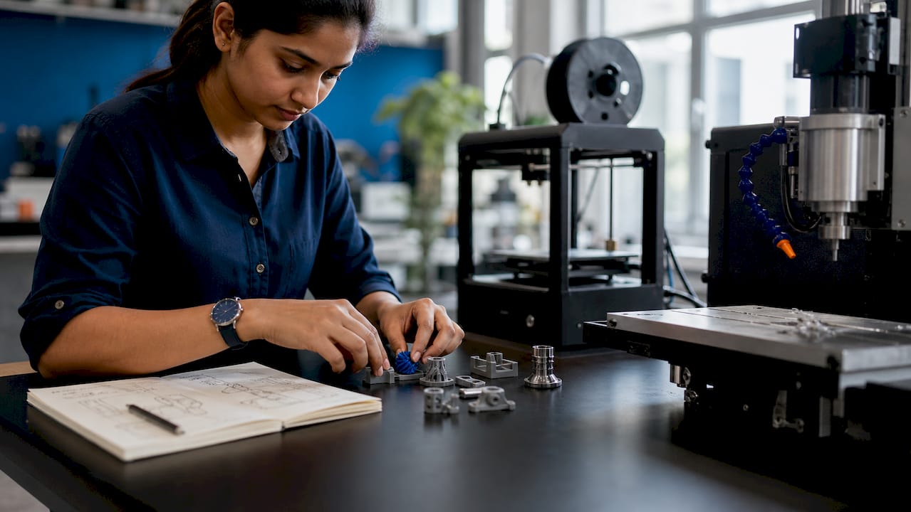
Additive manufacturing is the most widely used family of rapid prototyping methods because it requires no tooling, handles complex geometry without extra cost, and can produce a part overnight. But it is not always the right choice, and understanding the differences between methods helps you pick the one that actually answers your design question.
| Method | Speed | Typical Cost | Common Materials | Accuracy |
|---|---|---|---|---|
| FDM (3D printing) | Fast | Low | PLA, ABS, PETG, Nylon | Moderate |
| SLA (resin printing) | Fast | Low–Medium | Photopolymer resins | High |
| SLS (laser sintering) | Medium | Medium | Nylon, TPU, composites | High |
| CNC machining | Medium–Fast | Medium–High | Metals, engineering plastics | Very high |
| Wire EDM | Slower | High | Conductive metals | Extremely high |
| Vacuum casting | Medium | Medium | Polyurethane resins | High |
Additive methods (FDM, SLA, SLS) excel when you need a part fast and the design is geometrically complex. FDM is the workhorse for early concept models. SLA produces smooth surfaces suited for appearance prototypes or parts that need fine detail. SLS builds without support structures, which makes it useful for assemblies and flexible geometries.
Subtractive methods like CNC milling and turning become the right call when the prototype needs to behave like the production part. If you are testing mechanical load, thread engagement, or tight dimensional tolerances, a machined metal prototype gives you data that a 3D-printed plastic part simply cannot. CNC machining is also the standard path when the production process itself will be subtractive, because the prototype and the final part share the same material properties.
Wire EDM occupies a specific niche: parts with intricate internal profiles, sharp internal corners, or extremely tight tolerances in conductive metals. For firearm components, aerospace brackets, and precision tooling inserts, wire EDM precision often produces prototype geometry that no other method can match.
Vacuum casting bridges the gap between 3D printing and injection molding. You produce a master pattern, create a silicone mold, and cast urethane parts that closely replicate the properties of production thermoplastics. It works well for small batches of 10–50 parts when you need production-like material behavior without paying for hard tooling.
Selecting a method comes down to one question: what does this prototype need to prove? Match the method to the test, not to habit or convenience.
What are the key benefits of rapid prototyping?
Rapid prototyping reduces development time and cost by surfacing design problems early, when fixing them is cheap. Discovering a fatal flaw just before a product launch, after tooling has been cut and production scheduled, means starting over. Catching that same flaw in a prototype that cost a few hundred dollars to build changes the entire economics of product development.
The core advantages:
- Faster design validation. Physical prototypes answer questions that CAD renders cannot. You learn how a part feels in the hand, whether it assembles correctly, and whether it survives the load it was designed for, all before any production tooling exists.
- Lower cost of iteration. Changing a CAD file and rebuilding a prototype costs a fraction of modifying a production mold or retooling a machining fixture.
- Better stakeholder communication. A physical model communicates design intent more clearly than a drawing or a 3D render. Engineers, clients, and end users can all interact with it and give feedback grounded in real experience rather than interpretation.
- Multiple design options in parallel. You can build two or three variants of a feature simultaneously, test them side by side, and make a data-driven decision rather than a judgment call.
- Reduced risk before tooling investment. Committing to hard tooling without a validated prototype is one of the highest-risk decisions in manufacturing. Rapid prototyping gives you the evidence to make that commitment with confidence.
- Ergonomics and fit testing. Physical prototypes let you evaluate human factors, clearances, and assembly sequences in ways that digital simulation approximates but never fully replicates.
The form, fit, and function testing that rapid prototyping enables is particularly valuable in regulated industries like aerospace and defense, where a design change after certification can cost more than the original development program.
What are the limitations of rapid prototyping?
Rapid prototyping is not a substitute for production-grade manufacturing, and treating it as one leads to bad decisions. The limitations are real and worth understanding before you commit to a method or draw conclusions from a prototype’s performance.
- Material fidelity gaps. A 3D-printed prototype in PLA or photopolymer resin does not behave like an injection-molded nylon part or a machined aluminum component. Strength, thermal resistance, and surface finish all differ, sometimes dramatically.
- Size constraints. Every fabrication system has a build envelope. Large parts either require splitting into sections and bonding, or they exceed what the equipment can produce at all.
- Per-unit cost at volume. Additive methods are cost-effective for one to a few parts. At higher quantities, the per-unit cost of 3D printing often exceeds what injection molding or high-volume machining would cost, which is why prototyping methods rarely translate directly to production.
- Dimensional accuracy limits. FDM and SLA prototypes carry tolerances that are acceptable for concept validation but not for testing precision fits or mechanical interfaces. CNC machining closes that gap but adds time and cost.
- Risk of over-reliance. A prototype that passes a test is not a guarantee the production part will. Differences in material, process, and scale can introduce failure modes that the prototype never exposed.
- Overbuilding the first version. Spending too much time and money on a highly polished prototype before the core concept is validated wastes resources and slows the iteration cycle that makes rapid prototyping valuable in the first place.
The right mindset, as the HBS approach to rapid prototyping frames it, is to test assumptions quickly in the real world rather than perfect early versions. A prototype that answers one specific question well is more useful than a beautiful model that answers none.
Where is rapid prototyping used across industries?
Rapid prototyping shows up wherever the cost of a late-stage design error is high and the pressure to move fast is real. That covers a wide range of industries and use cases.
- Aerospace and defense. Design teams use SLA and CNC-machined prototypes to validate bracket geometry, clearances, and assembly sequences before committing to flight-grade hardware. Machiningtechllc’s prototyping expertise for aerospace supports exactly this kind of early-stage validation from its 70,000 square foot facility in Webster, Massachusetts.
- Firearm components. Tight tolerances and regulatory requirements make early physical validation non-negotiable. CNC-machined and wire EDM prototypes confirm dimensional accuracy and function before production runs begin.
- Industrial machinery. Engineers prototype housings, brackets, and custom fixtures to verify fit and manufacturability before ordering production quantities.
- Medical devices. Ergonomics, assembly sequences, and sterilization compatibility all get tested on prototypes before regulatory submissions.
- Consumer products. Industrial designers use appearance prototypes to gather user feedback and refine form before tooling decisions are made.
- Specialty materials. Glass components, for example, follow a prototyping workflow that mirrors the broader rapid prototyping process, validating geometry and optical properties before committing to production molds.
- Small-batch manufacturability testing. Before scaling a part to high-volume production, manufacturers run prototype batches to identify fixturing challenges, cycle time estimates, and process risks.
Machiningtechllc has served aerospace, defense, and firearm manufacturing clients since 1985, optimizing part prototyping from single prototypes through full production runs using CNC milling, turning, Hydromat systems, and wire EDM.
Is rapid prototyping the same as 3D printing?
No, and the distinction matters when you are choosing a method. Rapid prototyping is a design strategy; 3D printing is one manufacturing technology often used to execute that strategy. Conflating the two leads engineers to default to 3D printing when a different method would produce a more useful prototype.
Here is how they differ:
- Rapid prototyping is the goal: build something testable as fast as possible, learn from it, and iterate. It is process-agnostic.
- 3D printing (additive manufacturing) is a specific fabrication method. It is the most common tool for rapid prototyping because it requires no tooling and handles complex geometry, but it is one option among several.
- CNC machining is often the better choice when the prototype needs to replicate the mechanical properties of the production part, as noted in the difference between rapid prototyping and 3D printing.
- Wire EDM and vacuum casting serve specific prototype needs that neither 3D printing nor standard CNC machining covers well.
The practical implication: do not let the availability of a 3D printer drive your method selection. Ask what the prototype needs to prove, then choose the fabrication method that answers that question most accurately.
Pro Tip: When mechanical property accuracy matters, such as for load-bearing aerospace brackets or precision firearm components, CNC machining produces a prototype that behaves like the production part. A 3D-printed version of the same geometry may look identical but fail under conditions the production part would handle without issue.
Key Takeaways
Rapid prototyping compresses the design-to-validation cycle by building testable models early, catching errors before tooling investment, and iterating quickly based on real physical feedback.
| Point | Details |
|---|---|
| Rapid prototyping is a strategy, not a technology | It uses multiple fabrication methods; 3D printing is one tool, not the definition. |
| Match the method to the test | CNC machining suits mechanical validation; FDM and SLA suit concept and appearance review. |
| Catch errors before tooling | Fixing a design flaw in a prototype costs far less than revising production tooling after the fact. |
| Prototypes answer specific questions | Build to test one assumption at a time; overbuilt first prototypes slow the iteration cycle. |
| Limitations are real | Material fidelity, size constraints, and per-unit cost all affect what a prototype can and cannot prove. |
Ready to move from prototype to production?
Machiningtechllc has been turning prototype designs into precision production parts since 1985, serving aerospace, defense, firearm, and industrial machinery clients from a 70,000 square foot facility in Webster, Massachusetts. Whether you need a single CNC-machined prototype to validate a critical fit or a full production run of complex components, the team brings the same equipment and process discipline to both.
Explore how contract machining accelerates OEM production from the prototype phase through high-volume delivery, with Hydromat systems, CNC milling and turning, and wire EDM all under one roof.