

TL;DR:
- Custom component fabrication involves multiple steps, from design and material selection to finishing and inspection, which directly impact quality, cost, and delivery. Effective planning and early collaboration prevent costly errors, with emphasis on proper material choice, accurate cutting, and thorough quality controls throughout the process. Success relies on continuous oversight, clear communication, and rigorous adherence to design-for-manufacturing principles.
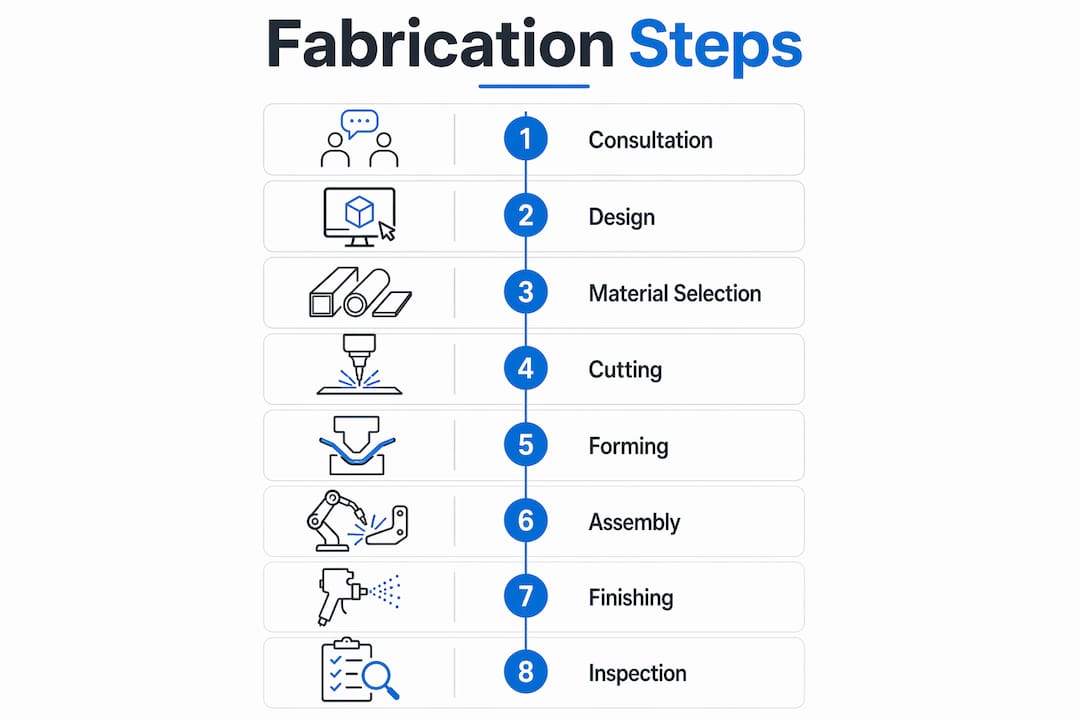
Custom component fabrication is a structured, multi-step process that converts design concepts into functional, specification-compliant parts using tools like CAD, CAM software, and CNC machinery. Each phase, from initial design through final inspection, directly affects part quality, cost, and delivery time. Engineers and project managers who understand every step in the fabrication workflow avoid the expensive surprises that derail production schedules. This guide covers the complete custom component fabrication steps, including material selection, cutting, forming, assembly, finishing, and quality control, with practical insights for professionals managing real production programs.
What are the essential custom component fabrication steps?
The fabrication process begins long before any metal is cut. Project consultation and design accuracy set the foundation for everything that follows. Early collaboration between clients and fabricators prevents costly design revisions that surface later in production. The goal at this stage is to lock in requirements before committing to tooling or material purchases.

CAD software such as SolidWorks or AutoCAD translates engineering intent into precise 3D models. CAM software then converts those models into machine instructions. Design for Manufacturing (DFM) analysis is the critical filter at this stage. It flags designs that are technically feasible but economically unviable to produce at scale.
Material selection drives total cost more than almost any other single decision in the fabrication workflow. The alloy you choose directly sets machine parameters: laser cutting speed, press brake force, and feed rates all change based on material properties. Steel alloys, aluminum, stainless steel, and titanium each behave differently under the same process conditions. Choosing the wrong material late in the project forces rework across multiple steps. You can review material machinability factors before finalizing your design to avoid this.
Pro Tip: Lock in your material specification before generating CAM toolpaths. Changing the alloy after programming forces a complete toolpath recalculation and can invalidate fixture designs.
| Tool or Software | Role in Fabrication | Stage |
|---|---|---|
| SolidWorks / AutoCAD | 3D modeling and design validation | Design |
| CAM software | Converts models to machine instructions | Pre-production |
| STEP / IGES file formats | Transfers geometry between systems | Design handoff |
| Laser cutters | High-precision sheet cutting | Cutting |
| CNC press brakes | Controlled metal bending | Forming |
How do cutting, shaping, and forming steps transform raw materials?
Cutting is the first physical transformation in the fabrication process guide. The method you choose determines dimensional accuracy, edge quality, and material waste. Laser cutting, plasma, waterjet, and sawing each serve different applications based on material thickness and required precision. Selecting the wrong method wastes material and introduces downstream fit problems.
Here is how the main cutting methods compare in practice:
- Laser cutting: Best for thin to medium gauge sheet metal with tight tolerances. Produces clean edges with minimal heat distortion on steel and aluminum.
- Plasma cutting: Faster than laser on thick plate but produces a wider kerf and rougher edge. Works well for structural components where edge finish is secondary.
- Waterjet cutting: No heat input, making it ideal for heat-sensitive materials like titanium or composites. Slower than laser but handles thick sections without warping.
- Sawing and shearing: Cost-effective for straight cuts on bar stock and sheet. Limited to simple geometries but fast for high-volume blanking operations.
Metal forming follows cutting and shapes blanks into three-dimensional components. Bending is the most common forming operation. CNC press brakes execute air bending, bottoming, and step bending with repeatable accuracy. Air bending uses less force and allows angle adjustments without changing tooling. Bottoming produces tighter tolerances but requires precise tooling matched to the material. Rolling forms cylindrical or conical shapes from flat sheet. Stamping uses dies to form complex geometries in a single press stroke, which is standard in high-volume custom part manufacturing.
Turret punches add holes, slots, and formed features to flat sheet before bending. CNC-controlled turret punches run multiple tool stations in sequence without manual tool changes. This reduces cycle time significantly on parts with many features.
Pro Tip: Always account for springback when programming bend angles. Aluminum springs back more than mild steel. Program the press brake to overbend by the calculated springback angle, then verify with a first-article bend before running the full batch.
What assembly methods are used for joining fabricated parts effectively?
Assembly is where individual fabricated parts become functional components or subassemblies. The joining method you select affects structural integrity, visual finish, and how easy the part is to service in the field. Welding methods like MIG, TIG, and spot welding are chosen based on material type and the application’s strength requirements.
MIG welding is fast and works well on mild steel and aluminum in production environments. TIG welding produces cleaner, more precise welds and is preferred for stainless steel, thin-gauge material, and applications where appearance matters. Spot welding joins sheet metal at discrete points using electrical resistance and is standard in automotive and enclosure manufacturing. Robotic welding systems deliver consistent weld quality at high volume and reduce labor cost per part.
| Assembly Method | Strength | Speed | Cost | Finish Quality |
|---|---|---|---|---|
| MIG welding | High | Fast | Low | Moderate |
| TIG welding | Very high | Slow | High | Excellent |
| Spot welding | Moderate | Very fast | Low | Good |
| Riveting | Moderate | Fast | Low | Good |
| Bolted fasteners | High | Moderate | Moderate | Good |
| PEM® fasteners | High | Fast | Moderate | Excellent |
Mechanical fastening with rivets, bolts, and threaded inserts is the right choice when parts need to be disassembled for maintenance. Rivets are permanent and vibration-resistant. Bolted connections allow field replacement of worn components. PEM® fasteners and tapping create strong threaded connections in thin sheet metal where standard nuts are impractical.
Jigs and fixtures are non-negotiable for assembly accuracy. A well-designed fixture holds parts in the correct position during welding or fastening, preventing angular distortion and misalignment. Skipping fixtures on complex assemblies produces parts that fail dimensional inspection.
How are finishing, quality control, and final inspection conducted?
Surface finishing is not cosmetic. It protects parts from corrosion, wear, and environmental exposure while meeting customer appearance specifications. Finishing processes like powder coating, galvanizing, anodizing, and painting each serve specific performance requirements. Choosing the wrong finish for the operating environment shortens part life and triggers warranty claims.
The main finishing options and their applications:
- Powder coating: Durable, chip-resistant finish for steel and aluminum. Available in a wide color range. Standard for enclosures, frames, and structural parts.
- Anodizing: Electrochemical process that hardens the aluminum surface. Provides corrosion resistance and accepts dye for color coding.
- Galvanizing: Hot-dip zinc coating for steel parts exposed to outdoor or wet environments. Provides long-term corrosion protection.
- PVD coating: Physical vapor deposition creates extremely hard, thin coatings. Used on cutting tools, firearm components, and high-wear parts.
- Wet painting: Flexible option for complex geometries or custom colors not achievable with powder.
Deburring and edge finishing precede any coating process. Sharp edges left from cutting or punching create safety hazards and cause coating adhesion failures. Non-destructive testing techniques including ultrasonic, magnetic particle, and X-ray inspection verify weld integrity and internal part quality without destroying the part. These methods are standard in aerospace, defense, and firearm manufacturing where part failure is not acceptable.
Final inspection verifies every dimension against the engineering drawing or 3D model. Coordinate measuring machines (CMMs) measure complex geometries to micron-level accuracy. Precision parts inspection closes the loop between the design specification and the delivered part.
Pro Tip: Integrate dimensional checks at the end of each fabrication stage, not just at final inspection. Catching a forming error before welding saves hours of rework. A first-article inspection report after the first complete part is the most cost-effective quality investment you can make.
What are common challenges and best practices in custom fabrication projects?
Design-for-manufacturing conflicts are the most expensive problem in custom fabrication. Insufficient DFM analysis produces parts that are technically correct on paper but require impractical tooling or excessive machine time to produce. The cost shows up in the quote, not the drawing. Catching these conflicts before production starts is the single highest-return activity in the entire workflow.
Prototyping and tooling optimization at early stages reduce rework costs and improve final production outcomes. A prototype run exposes fit problems, assembly sequence issues, and finish incompatibilities before you commit to full production tooling. The investment in a prototype is almost always less than the cost of a production change order.
Practical project management steps that reduce fabrication risk:
- Conduct a DFM review before releasing drawings to the shop floor. Involve the fabricator in this review, not just the design team.
- Specify material by alloy and temper, not just by generic name. “Aluminum” is not a specification. “6061-T6” is.
- Build a first-article inspection plan that covers every critical dimension before approving production quantities.
- Define weld symbols and finish requirements on the drawing, not in email threads. Verbal instructions create non-conformances.
- Schedule a mid-production audit on long runs to catch tool wear or process drift before it affects the full batch.
- Document lessons learned after each project and feed them back into the next DFM review cycle.
Complex part manufacturing requires that material selection, machine settings, and inspection criteria all align from the start. When any one of these three elements is defined late or changed mid-project, the others require revision. Managing these dependencies is the core skill of an effective fabrication project manager.
Key Takeaways
Successful custom component fabrication requires DFM analysis, precise material specification, and integrated quality checks at every stage, not just at final inspection.
| Point | Details |
|---|---|
| DFM analysis prevents costly errors | Review designs for manufacturability before releasing to production to avoid rework and tooling waste. |
| Material choice sets machine parameters | Alloy selection directly determines laser speed, press brake force, and coating compatibility. |
| Cutting method affects downstream quality | Match the cutting process to material thickness and tolerance requirements to minimize edge defects. |
| Assembly method drives serviceability | Choose welding or mechanical fastening based on joint strength needs and future maintenance requirements. |
| Finishing protects and validates the part | Apply the correct surface treatment for the operating environment and inspect every dimension before delivery. |
What I have learned from years of watching fabrication projects go sideways
The most common failure mode I see is not a machining error or a bad weld. It is a drawing that was never reviewed by anyone who would actually build the part. Engineers design in a vacuum, send a STEP file to the shop, and expect the fabricator to figure out the rest. That approach works until it does not, and when it fails, it fails expensively.
The fabricators who produce the best outcomes are the ones who push back early. They ask about bend radius relative to material thickness. They flag when a weld joint is inaccessible with standard equipment. They question tolerances that require a CMM to verify on a part that costs $12 to make. That kind of early friction saves weeks of rework.
Automation and precision machinery have genuinely changed what is achievable in custom part manufacturing. Hydromat systems, multi-axis CNC centers, and robotic welding cells produce consistency that manual processes cannot match at volume. But the technology only delivers its value when the design and material specification are correct going in. Garbage in, garbage out applies to a $2 million machining center just as much as it applies to a manual lathe.
The professionals who get the best results treat the fabrication workflow as a conversation, not a transaction. They stay involved from DFM review through first-article inspection. They do not disappear after sending the drawing. That level of engagement is what separates projects that ship on time from projects that become case studies in what not to do.
— Andrew
How Machiningtechllc supports your fabrication workflow
Machiningtechllc has operated out of its 70,000 square foot facility in Webster, Massachusetts since 1985, producing over 20 million parts annually for aerospace, defense, firearm manufacturing, and industrial machinery clients. The facility runs Hydromat systems, CNC milling, CNC turning, and wire EDM, covering the full range of precision machining operations that custom fabrication programs require.
For OEMs and industrial manufacturers who need reliable, high-volume output with tight tolerances, contract machining services at Machiningtechllc deliver faster production cycles and consistent part quality from prototype through full-scale production. The team works directly with engineers and project managers to align machine capabilities with design requirements from the start. Explore the full precision machining services to find the right fit for your next program.
FAQ
What are the first steps in custom component fabrication?
The first steps are project consultation, CAD-based design, DFM analysis, and material selection. These planning steps prevent costly changes once physical production begins.
How does material selection affect the fabrication process?
Material choice sets machine parameters including laser cutting speed, press brake force, and coating compatibility. Selecting the wrong alloy forces rework across multiple fabrication stages.
What cutting method is best for precision custom parts?
Laser cutting delivers the tightest tolerances on thin to medium gauge sheet metal. Waterjet cutting is the correct choice for heat-sensitive materials like titanium or composites.
When should non-destructive testing be used in fabrication?
Non-destructive testing using ultrasonic, magnetic particle, or X-ray inspection is required when weld integrity or internal part quality cannot be verified visually. It is standard practice in aerospace, defense, and firearm component manufacturing.
What is the most common cause of fabrication project delays?
Insufficient DFM analysis before production release is the leading cause of delays. It produces designs that require tooling changes, process revisions, or complete redesigns once manufacturing begins.
Recommended
- Custom Component Prototyping Process: 2026 Guide | Machining Technologies
- Master Precision Machining Workflow for Firearms Components | Machining Technologies
- Step-by-step precision part design for high-volume manufacturing | Machining Technologies
- Prototype Firearm Parts: A Guide for Engineers | Machining Technologies