

TL;DR:
- Tight tolerances in aerospace manufacturing are critical for safety, fit, and function, and depend on component criticality.
- Achieving these requires precise machining, strict process control, and comprehensive inspection standards governed by AS9100 and AS9102.
Tolerances in aerospace manufacturing are defined as the allowable dimensional variation that determines whether a component meets its design intent for safety, fit, and function. The role of tolerances in aerospace parts extends far beyond dimensional accuracy. Every micron of deviation affects structural integrity, assembly compatibility, and regulatory compliance under frameworks like AS9100, AS9102, FAA, and EASA. Tight tolerances prevent micro-gaps that cause fatigue cracks under repeated load cycles, which is why flight-critical parts like turbine blades and hydraulic actuators routinely require tolerances of ±0.001 inches or tighter. Machiningtechllc has built its aerospace machining practice around exactly these requirements since 1985.
What is the role of tolerances in aerospace parts by component type?
Aerospace tolerance requirements are not uniform. They scale with the functional criticality of each component, and the spread between the loosest and tightest specifications is wider than most general industrial engineers expect.
Tolerance ranges vary by application from ±0.025 mm for general airframe structures down to ±0.001 mm or tighter for critical sealing surfaces. That is a 25x difference in allowable variation across a single aircraft. Surface finish requirements follow the same gradient, ranging from Ra 1.6 μm for general surfaces to Ra ≤0.4 μm for critical bearing journals.
| Component type | Typical tolerance range | Surface finish |
|---|---|---|
| General airframe structures | ±0.010 to ±0.025 mm | Ra 1.6 μm |
| Precision interfaces and fits | ±0.002 to ±0.010 mm | Ra 0.8 μm |
| Bearing seats and hydraulic parts | ±0.002 to ±0.005 mm | Ra 0.4 μm |
| Critical sealing surfaces | ±0.001 mm or tighter | Ra ≤0.4 μm |
Bearing seats require concentricity ≤0.005 mm TIR in addition to their dimensional tolerance band. That means dimensional accuracy alone does not guarantee assembly fit. Tolerances specified in aerospace drawings often require complementary GD&T controls such as concentricity, flatness, and true position to fully define the part’s functional requirements.
Pro Tip: When reviewing a drawing for a new aerospace part, check for GD&T callouts alongside dimensional tolerances. A part that passes dimensional inspection can still fail assembly if its geometric controls are not verified separately.
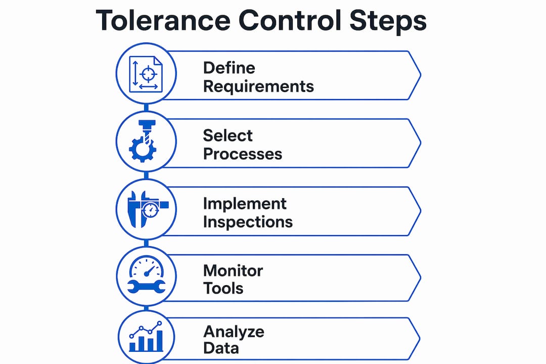
How do manufacturing processes and inspection standards ensure tolerance compliance?
Achieving aerospace tolerances requires more than capable machines. It demands a documented, repeatable production system governed by recognized quality standards.
AS9100 certification defines the quality management system requirements for aerospace manufacturers. NADCAP accreditation adds process-specific oversight for special processes like heat treatment, welding, and non-destructive testing. Together, these frameworks create the audit trail that FAA and EASA use to qualify or disqualify suppliers from aerospace supply chains.
First Article Inspection under AS9102 mandates documentation of actual measured values for every characteristic on the drawing. This is not a sampling approach. Every dimension, every GD&T callout, and every surface finish requirement must be measured and recorded on the first production article before volume manufacturing begins. FAA and EASA use this traceability to disqualify non-compliant suppliers.
Coordinate Measuring Machines (CMM) are the standard metrology tool for verifying complex aerospace geometries. CMM inspection captures three-dimensional data across multiple features simultaneously, which is the only practical way to verify true position and concentricity on complex parts. Continuous in-process monitoring supplements CMM inspection by catching tolerance drift before it produces scrap.
The most common sources of tolerance drift in production are:
- Tool wear: Cutting edges degrade progressively, shifting dimensions toward the tolerance boundary.
- Thermal effects: Heat generated during cutting causes workpiece and fixture expansion, which shifts feature locations.
- Fixturing inconsistency: Variation in clamping force or locating contact changes part position between setups.
- Spindle runout: Bearing wear in the machine spindle introduces radial error that compounds with tight-tolerance features.
Pro Tip: Build tool life limits into your process control plan before you see tolerance drift, not after. Replacing inserts at a defined interval costs far less than a CMM rejection at the end of a production run.
What challenges do aerospace materials and assemblies pose for tight tolerances?
Aerospace materials are selected for performance under extreme conditions, not for ease of machining. That trade-off creates real difficulty when holding micron-level tolerances across a full production run.
Machining Inconel requires cutting speeds 5–10 times lower than steel. Titanium causes tool wear at 5–10 times the rate seen with aluminum. Both materials concentrate heat at the cutting zone, which accelerates dimensional drift and demands more frequent tool changes. Aluminum alloys machine more freely but are prone to springback and burr formation at tight-tolerance features.
The challenge compounds at the assembly level. A consistent 1-micron deviation across 50 mating surfaces accumulates to a 50-micron error that can prevent assembly entirely. This is tolerance stack-up, and it is the primary reason aerospace assemblies require statistical tolerance analysis during the design phase, not just individual part inspection.
American and international tolerance standards also diverge in ways that create manufacturing errors when drawings cross borders. ISO 2768mk applies general rules by feature size category, while ASME Y14.5 specifies tolerances explicitly per feature type. A shop trained on ISO conventions reading an ASME drawing can misinterpret which tolerance applies to a given feature, producing parts that are dimensionally within ISO limits but out of compliance with the drawing’s intent.
Strategies that reduce stack-up and material-related tolerance risk include:
- Statistical tolerance analysis (RSS method): Calculates the probable assembly variation from individual part tolerances rather than assuming worst-case accumulation.
- Datum scheme alignment: Ensuring all mating parts share the same datum reference frame eliminates a major source of geometric incompatibility.
- Matched machining: Machining mating pairs together in a single setup removes the relative error between them.
- Controlled thermal environment: Maintaining shop temperature within a defined range reduces thermal expansion variation between parts measured at different times.
Engineers must interpret tolerance requirements carefully to avoid costly manufacturing errors caused by differing global standards. This is not a theoretical risk. It is a documented source of non-conformance in international aerospace supply chains.
How can aerospace manufacturers optimize tolerance control for quality and throughput?
Optimizing tolerance control is not about chasing the tightest possible specification on every feature. It is about applying the right level of control where function demands it and reducing unnecessary inspection burden everywhere else.
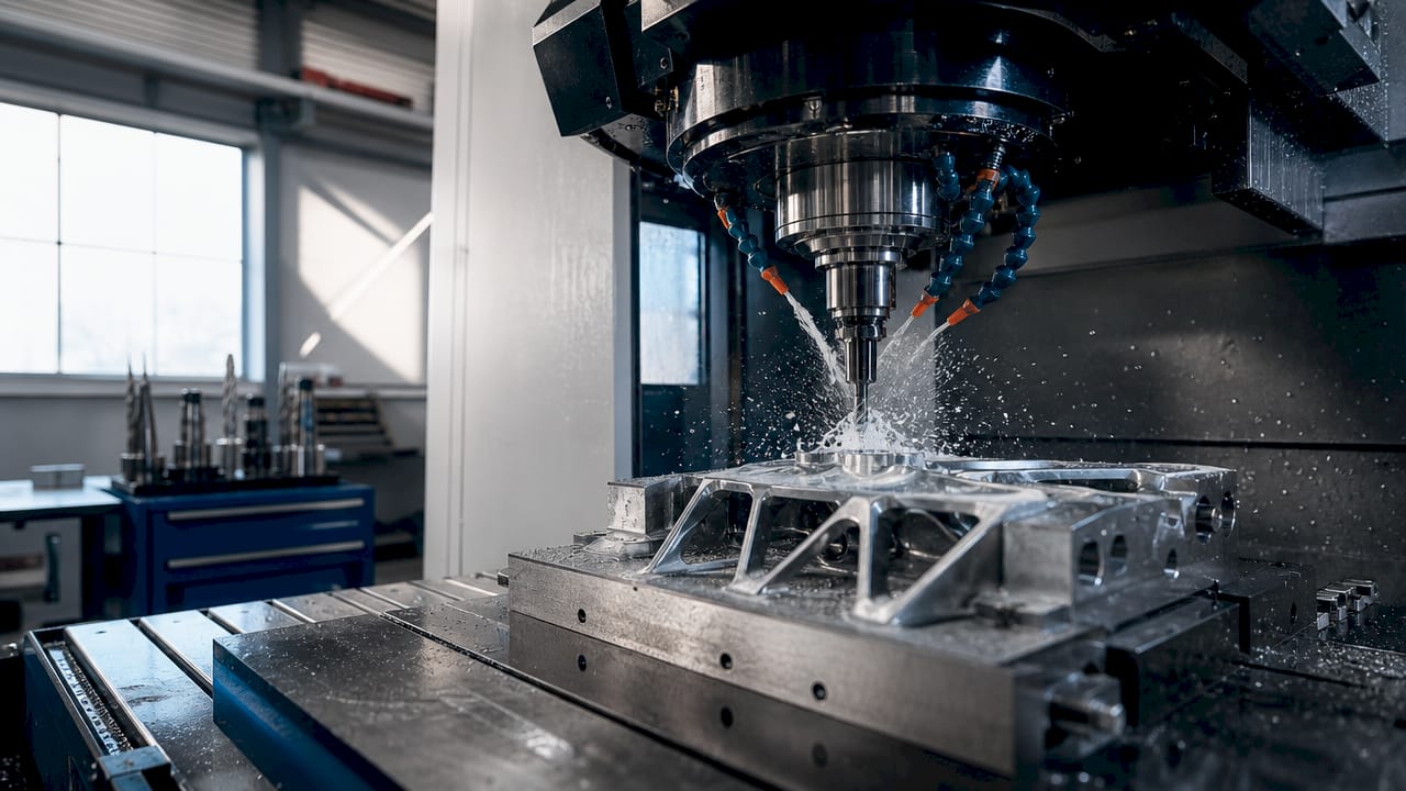
Manufacturing success in aerospace depends on strict process discipline and stable production conditions, not machine capability alone. A five-axis machining center with 0.001 mm positioning accuracy still produces out-of-tolerance parts if the fixturing shifts or the coolant temperature is uncontrolled. Process stability is the foundation.
Advanced 5-axis machining prevents distortion and improves fatigue life when working with high-performance aerospace materials. Machining complex features in a single setup eliminates the repositioning errors that accumulate when a part is moved between multiple machines. For multi-axis machining in aerospace, this is the primary argument for the investment.
Stable tooling and effective fixturing are as important as machine accuracy. Shrink-fit toolholders reduce runout compared to collet chucks. Hydraulic or zero-point fixturing systems deliver repeatable clamping force and location across every cycle in a production run.
Tolerance specification strategy also affects throughput directly. Specifying tighter tolerances than function requires forces every part through additional inspection steps. The practical approach is to specify tolerances only where functionally necessary and use standard tolerances for non-critical features. This reduces inspection time without compromising the parts that actually matter.
Process discipline requires maintaining a 4:1 ratio between measurement uncertainty and part tolerance at minimum. For the tightest aerospace tolerances, a 10:1 ratio is the target. That means a ±0.001 mm tolerance requires a measurement system with uncertainty no greater than ±0.0001 mm. CMM calibration schedules and gauge R&R studies are not optional overhead. They are the mechanism that makes tolerance control credible.
Pro Tip: Run a gauge R&R study before production begins on any new aerospace part. If measurement system variation consumes more than 10% of your tolerance band, your inspection results are unreliable regardless of how well the machine performs.
Key takeaways
Tight tolerances in aerospace manufacturing are a direct safety requirement, not a quality preference, and every process decision must support their consistent achievement.
| Point | Details |
|---|---|
| Tolerances scale with criticality | Aerospace specs range from ±0.025 mm for structures to ±0.001 mm for sealing surfaces. |
| GD&T controls are mandatory | Dimensional accuracy alone does not confirm assembly fit without concentricity, flatness, and true position verification. |
| AS9100 and AS9102 govern compliance | FAI documentation and traceability are required for FAA and EASA supplier qualification. |
| Stack-up demands early analysis | A 1-micron error across 50 interfaces accumulates to 50 microns, enough to prevent assembly. |
| Process discipline beats machine specs | Stable fixturing, controlled tooling, and thermal management determine whether tolerances hold across a production run. |
Tolerances are a process problem, not just a machine problem
After years of working with aerospace manufacturing requirements, the pattern I see most often is this: engineers focus on machine capability and overlook process stability. A shop buys a high-accuracy machining center, runs a capability study on a clean part, and declares the process qualified. Then production starts, tool wear sets in, the coolant temperature drifts, and the first CMM report shows a trend toward the tolerance boundary.
The machines matter. But the process around the machine is what actually holds tolerances across thousands of parts. Fixturing discipline, tool life management, thermal compensation, and measurement system integrity are where aerospace tolerance control is won or lost. I have seen shops with older equipment consistently outperform shops with newer machines because their process controls were tighter.
The other issue I see regularly is over-tolerancing. Engineers apply tight tolerances across an entire drawing when only three or four features actually drive assembly function. Every tight-tolerance feature adds inspection time and rejection risk. Audit your drawings against the assembly’s functional requirements before you release them to the shop floor. You will find features that can be relaxed without any impact on performance, and that reduction in inspection burden directly improves throughput.
The materials challenge is real and is getting harder as more programs specify titanium and nickel alloys for weight and temperature performance. Plan your tool change intervals conservatively, validate your cutting parameters on representative material lots, and build thermal compensation into your process from the start. Waiting until you see drift in your CMM data is too late.
— Andrew
Machiningtechllc: precision aerospace machining built for tight tolerances
Machiningtechllc has delivered precision aerospace components from its 70,000 square foot facility in Webster, Massachusetts since 1985. The operation produces over 20 million parts annually using CNC milling, turning, wire EDM, and Hydromat systems, all configured for the tight tolerances aerospace programs demand.
The team at Machiningtechllc works directly with aerospace OEMs on tolerance-critical programs, from first article through full-volume production. Process controls, fixturing discipline, and CMM-based inspection are built into every production run. For engineers who need a contract machining partner with the process depth to hold aerospace tolerances at scale, precision parts manufacturing at Machiningtechllc is the place to start. Review the full list of machining services to see where Machiningtechllc fits your program requirements.
FAQ
What is the tightest tolerance achievable in aerospace machining?
Critical sealing surfaces and precision interfaces in aerospace routinely require tolerances of ±0.001 mm or tighter. Achieving these requires CMM verification with a measurement system uncertainty of ±0.0001 mm or better.
Why do aerospace tolerances differ from general industrial tolerances?
Aerospace parts operate under extreme loads, temperatures, and vibration cycles where dimensional variation directly affects structural integrity and safety. General industrial machining typically holds ±0.025–0.050 mm, while aerospace precision interfaces require ±0.002–0.010 mm.
What is tolerance stack-up and why does it matter in aerospace assemblies?
Tolerance stack-up is the accumulation of individual part variations across multiple mating interfaces. A 1-micron deviation repeated across 50 surfaces produces a 50-micron total error that can prevent assembly of large aerospace structures.
How does AS9102 First Article Inspection support tolerance compliance?
AS9102 requires documented measurement of every drawing characteristic on the first production article, creating a traceable record that FAA and EASA use to qualify suppliers and verify that the manufacturing process can consistently meet the design intent.
What is the difference between ISO 2768 and ASME Y14.5 for aerospace drawings?
ISO 2768mk assigns general tolerances by feature size category, while ASME Y14.5 specifies tolerances explicitly per feature type. Misreading which standard applies to an aerospace drawing is a documented source of non-conformance in international supply chains.
Recommended
- How to specify machining tolerances for precision | Machining Technologies
- Step-by-step precision part design for high-volume manufacturing | Machining Technologies
- Firearm parts machining: ±0.001" tolerance ensures reliability | Machining Technologies
- Best practices in tolerances for aerospace precision machining | Machining Technologies