

Many aerospace engineers believe that 5-axis machining automatically delivers superior results for every component. In reality, selecting the right multi-axis approach requires matching technology to part geometry, production volume, and cost constraints. This guide clarifies the distinctions between 3-axis, 4-axis, and 5-axis simultaneous machining, explains how these technologies improve efficiency and precision in aerospace manufacturing, and provides practical frameworks for procurement specialists evaluating supplier capabilities. You’ll learn when to specify 3+2 positioning versus full simultaneous 5-axis, how to overcome thin-wall machining challenges, and what design considerations drive optimal outcomes.
Table of Contents
- Key takeaways
- Understanding multi-axis machining: types and capabilities
- Advantages of multi-axis machining for aerospace and defense parts
- Challenges and nuances in multi-axis machining for thin-walled aerospace components
- Choosing the right multi-axis machining strategy for aerospace manufacturing
- Enhance your aerospace manufacturing with precision multi-axis machining
- Frequently asked questions about multi-axis machining
Key Takeaways
| Point | Details |
|---|---|
| Axis approach differences | Know when to use three plus two, four axis, or full five axis based on part geometry and production goals. |
| Efficiency gains | Multi axis reduces setups by up to 65 percent and shortens cycle times with proper toolpath optimization. |
| Surface finish gains | Simultaneous five axis improves surface finish enabling Ra values around 0.25 to 0.40 micrometers on aluminum and titanium alloys. |
| Procurement guidance | Verify supplier capabilities for true simultaneous motion by requesting sample parts and toolpath documentation and choosing providers whose axis capabilities match the component requirements. |
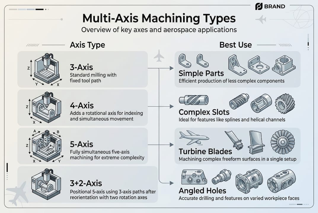
Understanding multi-axis machining: types and capabilities
Multi-axis machining refers to CNC processes that move cutting tools along more than three linear axes. Traditional 3-axis machines operate on X, Y, and Z coordinates, limiting tool approach angles and requiring multiple setups for complex geometries. Adding rotational axes dramatically expands manufacturing capabilities.
4-axis machining introduces a single rotational axis, typically labeled A-axis, allowing the workpiece to rotate during cutting. This configuration excels at cylindrical parts, engraved components, and features requiring continuous rotation. Aerospace applications include turbine shafts and landing gear components where radial features demand consistent tool engagement around a central axis.
5-axis simultaneous machining moves all five axes continuously throughout the cutting operation. The machine maintains optimal tool angle dynamically, enabling freeform surface machining without repositioning. This capability proves essential for turbine blades, impellers, and complex aerospace structures where surface quality and geometric accuracy cannot tolerate setup transitions.
3+2-axis machining, also called positional 5-axis, rotates the workpiece to a fixed angle, then performs traditional 3-axis cutting. After completing features at one orientation, the machine repositions for the next set of operations. This approach offers some multi-axis benefits without the programming complexity of full simultaneous motion.
| Axis type | Movement capability | Typical aerospace applications | Primary advantage |
|---|---|---|---|
| 3-axis | Linear X, Y, Z only | Flat components, simple pockets | Cost-effective, widely available |
| 4-axis | Linear + single rotation | Turbine shafts, cylindrical housings | Continuous radial machining |
| 5-axis simultaneous | All axes move together | Turbine blades, complex titanium structures | Optimal tool angle, single setup |
| 3+2-axis | Positional rotation + 3-axis cutting | Multi-face brackets, prismatic components | Simpler programming than simultaneous |
When evaluating best CNC machining providers, verify their specific axis capabilities match your component requirements. A supplier with 5-axis equipment may primarily run 3+2 operations, limiting their ability to machine truly complex freeform surfaces. Request sample parts and toolpath documentation to confirm simultaneous motion expertise.
The distinction between simultaneous and positional 5-axis significantly impacts surface finish, cycle time, and achievable geometries. Simultaneous motion eliminates witness marks from setup transitions and maintains consistent chip load throughout complex contours. Positional approaches work well for parts with distinct faces but struggle with organic shapes requiring continuous curvature.
Advantages of multi-axis machining for aerospace and defense parts
Multi-axis machining delivers measurable improvements in production efficiency and part quality. Setup reduction reaches 65% for aerospace alloys, directly cutting labor costs and minimizing error accumulation from workpiece repositioning. Each setup introduces potential misalignment, and eliminating these transitions improves dimensional accuracy across critical features.
Surface finish improvements of 40% enable aerospace components to meet stringent quality standards without secondary operations. Multi-axis machining achieves Ra 0.25-0.40 μm finishes on aluminum 7075, 7050, and titanium alloys by maintaining optimal tool engagement angles throughout cutting. This consistency eliminates the directional variations common in 3-axis machining where tool approach changes between setups.
Cycle time reductions average 60% when workpiece setup and toolpath optimization receive proper attention. Single-setup machining eliminates load/unload cycles, fixture changes, and setup verification steps that consume non-cutting time. However, these gains require careful kinematics planning to avoid feedrate drops during axis transitions.
Key efficiency improvements include:
- Reduced fixture requirements lower tooling costs and simplify production planning
- Continuous cutting paths minimize tool retracts and air moves
- Optimal chip evacuation from maintained tool angles prevents recutting
- Elimination of setup-to-setup datum transfer errors improves tolerance capability
- Single-operation completion enables better production flow and scheduling
Complex aerospace geometries become manufacturable through multi-axis capabilities. Turbine blades with twisted airfoil profiles, thin-walled titanium structures, and integrated impeller designs require continuous tool angle adjustment impossible with 3-axis equipment. The technology enables benefits of precision machining previously achievable only through costly EDM or grinding operations.
Pro Tip: Optimize toolpath strategies by analyzing workpiece orientation before programming. Tilting the part 15-30 degrees often improves tool access to critical features while maintaining rigidity. Test multiple orientations in CAM software to identify the setup minimizing tool length and maximizing cutting efficiency.
Multi-axis machining achieves Ra 0.25-0.40 μm surface finishes on aerospace alloys, meeting critical quality standards without secondary polishing operations. This capability reduces processing steps and ensures consistent surface integrity across complex geometries.
The technology particularly excels with difficult-to-machine materials common in aerospace applications. Titanium, Inconel, and hardened steels benefit from the consistent chip load and optimal rake angles multi-axis machining maintains. These materials work-harden rapidly under interrupted cuts, making the continuous engagement possible with simultaneous 5-axis essential for maintaining tool life and surface quality.
Production throughput improvements extend beyond cycle time reduction. Machining trends toward faster lead times reflect how single-setup operations simplify scheduling, reduce work-in-process inventory, and enable faster response to engineering changes. When design modifications occur, updating a single program proves faster than coordinating changes across multiple setups.
Challenges and nuances in multi-axis machining for thin-walled aerospace components
Thin-walled structures under 2mm thickness present significant machining challenges. These components experience chatter and deformation due to low rigidity, requiring specialized strategies to maintain dimensional accuracy. Vibration during cutting causes surface defects, dimensional errors, and potential part rejection in aerospace applications where tolerance bands remain tight.
Stability lobes define cutting parameter combinations that avoid resonant frequencies. Analyzing the workpiece-fixture-machine system identifies spindle speeds and depths of cut that minimize vibration. Process damping, which occurs at low cutting speeds where the tool’s flank face contacts the workpiece, provides additional stability for thin sections.
Toolpath selection critically impacts thin-wall success. Flow optimal strategies using 4mm tip radius tools with radial engagement of 0.05mm distribute cutting forces while maintaining material removal rates. These approaches require careful programming to balance productivity against mechanical stress on delicate features.
Critical parameters for thin-wall aerospace machining:
- Minimum stable wall thickness of 1.5-2mm for defense applications
- Cutting speeds up to 700 m/min used cautiously due to induced tensile stress
- Radial engagement limited to 0.05-0.1mm to control deflection
- Axial depth of cut managed to prevent chatter initiation
- Tool tip radius optimized for surface finish without excessive rubbing
Kinematics limitations affect feedrates during multi-axis motion. As rotary axes accelerate and decelerate, linear axis speeds must adjust to maintain programmed surface speed. Poor toolpath planning causes feedrate drops that create witness marks and inconsistent surface finish. Advanced CAM systems compensate for these effects, but verification through simulation remains essential.
High-speed machining tempts engineers seeking faster cycle times, but thin aerospace walls require strategy over speed. Excessive cutting velocities generate heat and tensile stress that warp delicate features. Peer-reviewed research prioritizes controlled engagement over maximum spindle RPM for these applications.
Pro Tip: Conduct stability analysis before programming thin-wall components. Many CAM systems include stability lobe modules that predict chatter-free cutting parameters. Invest 30 minutes in this analysis to avoid hours of troubleshooting and potential scrap.
Material properties influence thin-wall machining success. Aluminum 7075 and 7050 alloys machine more predictably than titanium due to lower cutting forces and better thermal conductivity. Titanium’s poor heat dissipation concentrates thermal energy at the cutting edge, requiring careful coolant application and conservative parameters on thin sections.
Fixturing strategy becomes paramount for thin-walled components. Traditional clamping forces deform flexible features, so vacuum chucks, wax mounting, or custom soft jaws distribute holding pressure. Some aerospace manufacturers use sacrificial support structures machined away in final operations to maintain rigidity throughout processing.
The complex part manufacturing strategies required for thin walls extend programming time and demand experienced machinists. Budget additional setup time for these components and expect iterative refinement of parameters during first article production. Document successful approaches for future orders to capture this process knowledge.
Choosing the right multi-axis machining strategy for aerospace manufacturing
Selecting between 3+2 positioning and simultaneous 5-axis machining requires analyzing part geometry, production volume, and cost constraints. Simultaneous 5-axis costs more in programming time, machine investment, and operator expertise, making it unsuitable for every application. Strategic selection maximizes manufacturing efficiency without unnecessary complexity.
Part geometry drives the primary decision. Prismatic components with distinct faces machined at different angles suit 3+2 positioning. The machine rotates to each face, then performs standard 3-axis operations. This approach simplifies programming and reduces cycle time compared to continuous 5-axis motion for these geometries.
Freeform organic shapes with continuous curvature require simultaneous 5-axis machining. Turbine blades, impellers, and sculptured mold surfaces need constant tool angle adjustment to maintain optimal cutting conditions. Attempting these geometries with 3+2 positioning creates witness marks at transition points and compromises surface quality.
Factors influencing strategy selection:
- Part complexity: Continuous curvature favors simultaneous, distinct faces suit 3+2
- Production volume: High volumes justify simultaneous 5-axis programming investment
- Tolerance requirements: Tightest tolerances benefit from single-setup simultaneous machining
- Available programming resources: 3+2 requires less specialized CAM expertise
- Machine tool capabilities: Verify kinematics support intended strategy
- Material characteristics: Difficult alloys benefit from optimized tool angles
| Strategy | Best applications | Primary advantage | Typical limitation |
|---|---|---|---|
| 3+2 positioning | Multi-face brackets, housings | Simpler programming, lower cost | Witness marks at transitions |
| Simultaneous 5-axis | Turbine blades, impellers, molds | Optimal surface finish, single setup | Higher programming complexity |
| Hybrid approach | Complex assemblies with mixed features | Balances efficiency and capability | Requires careful operation planning |
Design for manufacturability analysis guides optimal strategy selection. Collaborate with manufacturing engineers during design phases to identify features that drive multi-axis requirements. Sometimes minor design modifications eliminate the need for complex machining, reducing costs without compromising functionality.
Pro Tip: Request DFM analysis from potential suppliers during the quoting phase. Experienced manufacturers identify opportunities to simplify machining approaches through minor design adjustments. This collaboration often reduces costs 20-30% while maintaining or improving part performance.
Production volume influences the economic breakeven between strategies. Low-volume prototype runs may justify 3+2 positioning to minimize programming time, even if simultaneous 5-axis would improve quality. High-volume production amortizes programming costs across thousands of parts, making the investment in optimized simultaneous toolpaths worthwhile.
Supplier capabilities vary significantly in multi-axis machining. Some shops own 5-axis machines but lack programming expertise for complex simultaneous operations. Others specialize in these applications and maintain extensive toolpath libraries. Evaluate precision parts manufacturing quality through sample parts and detailed capability discussions rather than equipment lists alone.
The decision framework should prioritize manufacturing efficiency aligned with quality requirements. Overspecifying simultaneous 5-axis for simple geometries wastes resources, while underspecifying 3+2 for complex parts compromises quality. Balance technical requirements against practical constraints to optimize outcomes.
Consider why tight tolerances matter in aerospace machining when evaluating strategies. Tolerance stack-up from multiple setups often drives the need for single-setup simultaneous machining, even when geometry alone might permit 3+2 positioning. Calculate tolerance budgets early in the procurement process to inform strategy selection.
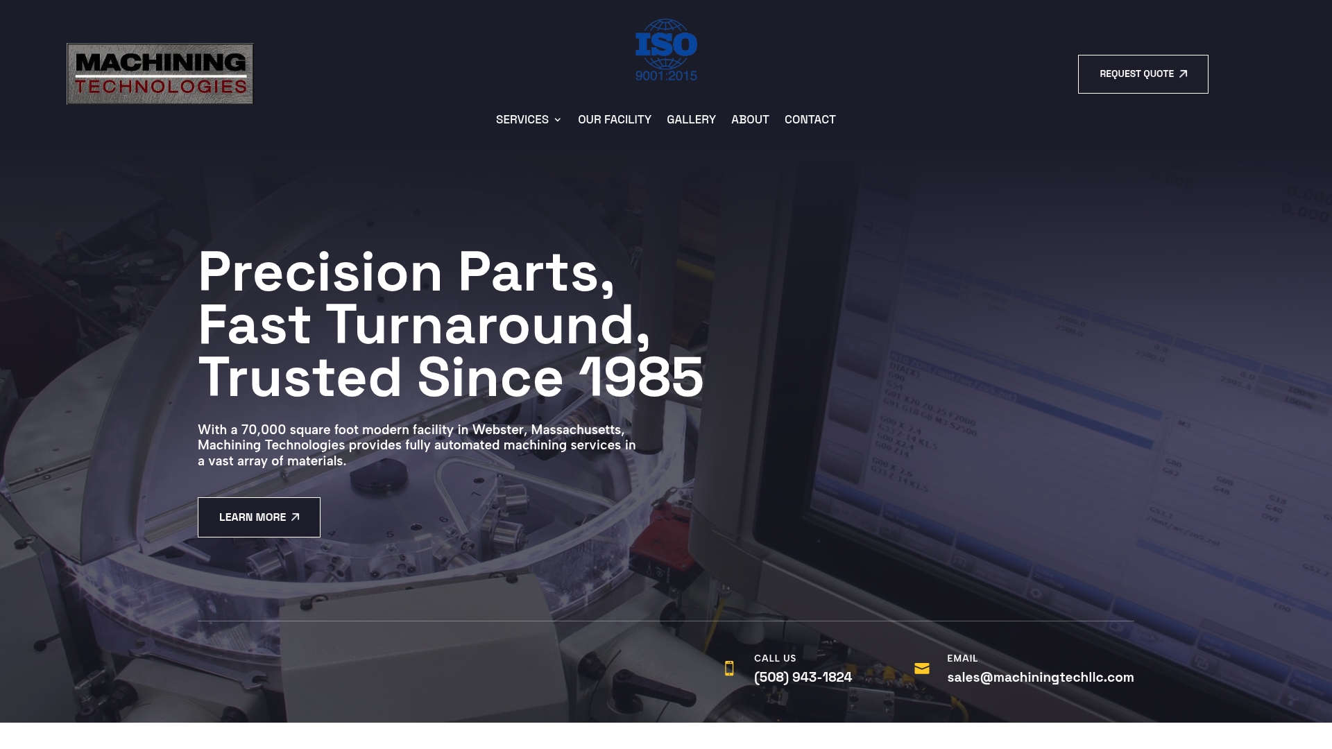
Enhance your aerospace manufacturing with precision multi-axis machining
Machining Technologies LLC delivers advanced multi-axis machining solutions for aerospace and defense components requiring exceptional precision. Our 70,000 square foot facility houses simultaneous 5-axis equipment alongside CNC milling and turning centers, enabling optimized strategies for every geometry. We specialize in thin-walled aluminum and titanium structures, applying stability analysis and flow optimal toolpaths to achieve consistent quality.
Our engineering team collaborates on DFM analysis to identify the most efficient machining approach for your components. Whether your parts require 3+2 positioning for multi-face features or full simultaneous 5-axis for complex organic shapes, we optimize toolpaths to minimize cycle times while maintaining precision parts manufacturing quality standards. Setup reduction strategies and single-operation processing improve throughput for high-volume aerospace production.
We serve defense industry applications requiring Ra 0.25-0.40 μm surface finishes and tight geometric tolerances. Our process controls ensure consistent results across production runs, with documented procedures for challenging thin-wall geometries. Explore our complete machining services to see how multi-axis capabilities integrate with our broader manufacturing solutions.
Pro Tip: Partner with manufacturers who invest in ongoing CAM software training and toolpath optimization. The difference between adequate and exceptional multi-axis machining lies in programming expertise, not just equipment ownership.
Precision multi-axis machining transforms complex aerospace designs into manufacturable reality. Our commitment to continuous improvement in toolpath strategies and process optimization ensures your components meet the most demanding specifications.
Frequently asked questions about multi-axis machining
What makes 5-axis machining different from 3-axis?
5-axis machines move cutting tools along three linear axes plus two rotational axes simultaneously, maintaining optimal tool angles throughout complex contours. 3-axis equipment moves only linearly on X, Y, and Z coordinates, requiring multiple setups for complex geometries. The additional rotational capability reduces setups by 65% and improves surface finish by 40% for aerospace components.
When should I specify simultaneous 5-axis instead of 3+2 positioning?
Specify simultaneous 5-axis for parts with continuous freeform surfaces like turbine blades or impellers where tool angle must adjust dynamically. Use 3+2 positioning for prismatic components with distinct faces machined at different angles. Simultaneous motion eliminates witness marks but requires more complex programming and higher machine investment.
How do you prevent chatter when machining thin-walled aerospace parts?
Thin walls under 2mm require stability lobe analysis to identify chatter-free cutting parameters, combined with process damping at controlled speeds. Flow optimal toolpaths with 4mm tip radius and 0.05mm radial engagement distribute forces while maintaining material removal. Proper fixturing and support structures also prove essential for maintaining rigidity during cutting.
What surface finish can multi-axis machining achieve on titanium?
Multi-axis machining achieves Ra 0.25-0.40 μm on titanium alloys through optimized tool angles and continuous engagement. This finish quality meets aerospace standards without secondary polishing operations. Success requires careful parameter selection, appropriate tooling, and effective coolant application to manage titanium’s poor thermal conductivity.
How do I evaluate a supplier’s true multi-axis capabilities?
Request sample parts demonstrating simultaneous 5-axis work, not just 3+2 positioning. Review their CAM software capabilities, programmer experience, and process documentation for thin-wall components. Ask about stability analysis procedures and toolpath optimization strategies. Equipment ownership matters less than programming expertise and process knowledge for complex geometries.
Recommended
- Why tight tolerances matter for aerospace machining | Machining Technologies
- Machining Trends 2026: 40% Faster Lead Times + 50% Tool Life | Machining Technologies
- Why choose custom machining for aerospace and defense | Machining Technologies
- Machining in defense industry: precision and innovation | Machining Technologies