

TL;DR:
- Part geometry influences 60–80% of CNC machining costs by determining tool access, cycle time, and tooling options. Addressing features like internal radii, wall ratios, and symmetry during the CAD phase can significantly reduce manufacturing expenses and improve part quality. Implementing design for manufacturability strategies and understanding geometry-tool interactions are essential for cost-efficient machining and high-quality production.
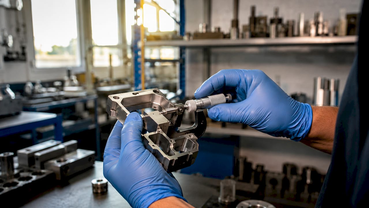
Part geometry is the single greatest driver of CNC machining cost, cycle time, and tooling selection. Before a single chip is cut, the shape of your part determines which tools can reach critical features, how fast those tools can run, and how many setups the job requires. Part geometry accounts for 60–80% of total CNC machining costs. That figure means design decisions made in CAD carry more financial weight than machine speed, operator skill, or material price. Understanding why part geometry impacts machining gives manufacturing engineers and production managers the leverage to control outcomes before the job hits the floor.
Which geometric features drive machining complexity?
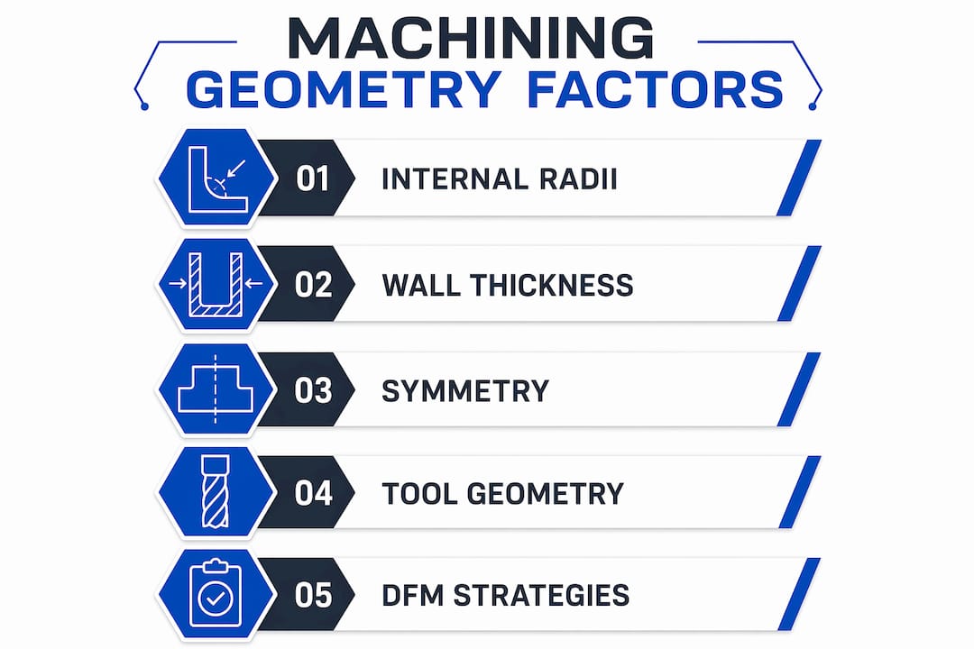
The impact of geometry on machining is most visible in four specific feature types: internal corner radii, wall thickness ratios, pocket depth, and part symmetry. Each one constrains tooling choices and feeds directly into cycle time and cost.
Internal corner radii
Internal corners are the most common geometry-driven cost driver in CNC work. A tight internal radius forces the use of a smaller end mill, which runs slower and deflects more under cutting load. Internal corner radii sized at least 1/3 of pocket depth enable faster machining and reduce tool breakage. When radii fall below that threshold, micro-endmills must cut at 4–6 times slower feed rates, or the job requires a secondary EDM operation adding $15–$35 per part. That cost compounds fast across high-volume runs.
Pro Tip: Design corner radii 5–10% larger than the tool radius you plan to use. Exact radius matching forces tool deceleration in corners, increasing both cycle time and tool wear. A slightly oversized radius keeps the tool moving at full speed through the cut.
Wall thickness and pocket depth ratios
Thin walls and deep pockets create two separate problems: vibration and tool deflection. Wall height-to-thickness ratios above 8:1 require special fixturing and reduce feed rates by 60–75%, which directly multiplies cycle time. That is not a minor inefficiency. It can turn a 10-minute operation into a 40-minute one. Deep pockets with depth-to-width ratios above 3:1 force the use of long-reach tools that flex under cutting forces, doubling or quadrupling cycle time.
Symmetry and wall uniformity
Asymmetric parts generate uneven cutting forces during machining. Those forces cause chatter, dimensional drift, and surface defects that show up at inspection. Balanced mass distribution and uniform wall thickness improve dimensional stability throughout the cut. A part that looks symmetric in a CAD rendering may still have asymmetric mass distribution that causes real machining problems. Experienced engineers check wall thickness uniformity as a separate step from visual symmetry review.
How does tool geometry interact with part geometry?
Tool geometry and part geometry are not independent variables. They interact at the cutting edge, and that interaction governs surface finish, burr formation, tool wear, and dimensional accuracy.
The three tool parameters that matter most relative to part features are edge radius, rake angle, and relief angle. Edge radius has the largest effect on surface quality. Research on titanium alloy milling shows that optimized edge radius reduces surface roughness by 11% and white layer thickness by 30%. White layer is a thermally damaged surface zone that causes premature part failure in aerospace and defense applications. Controlling it through tool geometry selection is more reliable than adjusting machine parameters after the fact.
Coatings and micro-textures on cutting tools also change how part geometry behaves under load. Micro-textured coated blunt edge tools reduce burr height by 22% in titanium milling. Burr removal is a non-value-added operation that adds labor and inspection time. Eliminating it through tool selection is a direct cost reduction.
The broader principle is that machining performance is capped by geometry-induced cutting forces, regardless of machine settings. You cannot overcome a bad geometry combination by running faster or slower. The geometry defines the ceiling. Laser-produced textures on cutting tools help minimize those cutting forces and maintain production quality when part geometry is fixed and cannot be changed.
Here is the practical sequence for matching tool geometry to part geometry:
- Identify the most constrained feature on the part, typically the smallest internal radius or thinnest wall.
- Select the largest tool diameter that fits that feature with a 5–10% radius clearance.
- Choose edge radius and coating based on material and surface finish requirements.
- Verify rake and relief angles against the depth-to-width ratio of any pockets.
- Simulate the toolpath in CAM software before cutting to confirm no deflection or interference issues.
Pro Tip: For titanium and hardened steel parts, prioritize edge radius specification over rake angle when selecting tools. Edge radius control has a larger measurable effect on surface integrity than rake angle adjustments in these materials.
What DFM strategies optimize geometry for efficient machining?
Design for Manufacturability, commonly called DFM, treats part geometry and tool selection as a single integrated problem rather than two sequential decisions. Early design decisions determine most per-part economics before cutting begins. That means the CAD phase is where cost is locked in, not the shop floor.
The table below compares common geometry choices and their machining impact:
| Design Choice | Machining Impact |
|---|---|
| Internal radius = tool radius | Tool decelerates in corners; higher wear and cycle time |
| Internal radius 5–10% larger than tool | Continuous cutting; lower wear and faster cycle |
| Wall height-to-thickness ratio above 8:1 | Feed rate drops 60–75%; special fixturing required |
| Wall height-to-thickness ratio below 4:1 | Standard fixturing; full feed rates achievable |
| Pocket depth-to-width ratio above 3:1 | Long-reach tools; cycle time doubles or quadruples |
| Pocket depth-to-width ratio below 3:1 | Standard tooling; predictable cycle times |
| Tight tolerances on non-mating features | Slower feeds; more inspection; higher reject rate |
| Tolerances matched to functional requirements | Faster feeds; reduced inspection burden |
Adhering to standard tooling sizes and recommended feature ratios reduces machining time by 30–50%. That is a measurable return on a design decision that costs nothing to implement in CAD. The most common missed opportunity in DFM is over-tolerancing. Over-tolerancing increases costs substantially. Tight tolerances on features that never contact another part slow feed rates, increase inspection frequency, and raise the reject rate without improving function.
The CAD/CAM integration approach that Machiningtechllc uses models the manufacturing process during the design phase. This means toolpath constraints, fixturing requirements, and feature ratios are evaluated before the design is released. DFM interventions at this stage routinely reduce per-part costs by 20–50% without changing the functional performance of the part.
How do challenging geometries affect machining performance?
Some geometry problems cannot be designed away. When you are working with a fixed part design, understanding the effects of difficult features helps you choose the right machining strategy.
The most common machining challenges due to geometry fall into three categories:
- Deep pockets and thin walls. Feed rates drop by 60–75% when wall ratios exceed 8:1. Cycle time increases proportionally. The mitigation is a combination of reduced axial depth of cut, higher spindle speed, and specialized long-reach tooling with vibration-damping properties.
- Asymmetric mass distribution. Parts with uneven mass generate variable cutting forces that cause chatter and dimensional drift. Asymmetric parts in CAD may cause machining issues despite appearing symmetric visually. The fix is careful part orientation and custom fixturing that supports the part at its heaviest sections.
- Small internal features requiring micro-tooling. Features below 0.040 inches in diameter require micro-endmills or wire EDM as a secondary operation. EDM adds $15–$35 per part and extends lead time. When the feature is non-functional at that scale, redesigning it to a larger size eliminates the cost entirely.
Multi-axis machining reduces the impact of complex geometry by repositioning the part to maintain optimal tool engagement angles. A 5-axis machine can reach undercuts and compound angles that would require multiple setups on a 3-axis machine. Each additional setup adds fixturing time, introduces potential for datum shift, and increases the risk of dimensional error. For complex part manufacturing, reducing setup count is one of the highest-leverage improvements available.
Part orientation during machining also affects thermal distortion. Heat generated during cutting distributes unevenly in asymmetric parts, causing warping that shows up after the part cools. Orienting the part so the heaviest section is closest to the fixture reduces thermal movement and improves final dimensional accuracy.
Key takeaways
Part geometry controls machining cost and quality more than any other single variable, and addressing it during the CAD phase delivers the highest return.
| Point | Details |
|---|---|
| Geometry drives 60–80% of cost | Design decisions in CAD lock in most per-part economics before machining begins. |
| Corner radii sizing is critical | Radii 5–10% larger than tool diameter enable continuous cutting and reduce tool wear. |
| Wall and pocket ratios set feed limits | Ratios above 8:1 or 3:1 cut feed rates by 60–75% and multiply cycle time. |
| Tool and part geometry interact directly | Edge radius selection controls surface roughness and white layer formation in critical materials. |
| DFM reduces costs by 20–50% | Integrating geometry and tooling decisions during CAD eliminates the most expensive machining constraints. |
What i’ve learned from watching geometry decisions play out on the floor
After years of working with complex part designs across aerospace, defense, and industrial machinery, the pattern I see most often is this: the most expensive machining problems were created in a CAD seat, not on the shop floor. A designer adds a sharp internal corner because it looks clean in the model. A tolerance gets copied from a similar part without checking whether it applies to a mating surface. A pocket gets made 0.050 inches deeper than necessary because the model looked better that way. Each decision seems trivial. Together, they can double the cost of a part.
The engineers who consistently produce the most machinable designs are the ones who have spent time on the floor watching what happens when their geometry hits a spindle. They understand that a 0.125-inch radius is not just a number in a drawing. It is a tool diameter, a feed rate, and a cycle time. That physical intuition is hard to teach from a textbook, but it is the difference between a part that runs at full speed and one that requires constant operator intervention.
The other thing I would stress is that DFM is not a one-time checklist. It is an ongoing conversation between design and manufacturing engineering. The best outcomes I have seen come from shops where that conversation starts at the concept stage and continues through first article inspection. Waiting until a part is in production to discover a geometry problem is the most expensive way to learn the lesson. The precision part design process works best when manufacturing constraints are built into the design criteria from day one, not retrofitted after the fact.
— Andrew
How Machiningtechllc handles complex part geometry
Machiningtechllc has been solving geometry-driven machining challenges since 1985, producing over 20 million parts annually from its 70,000 square foot facility in Webster, Massachusetts.
When a part design arrives with tight radii, deep pockets, or asymmetric features, the team evaluates geometry and tooling together before the first setup. That integrated approach is what keeps cycle times predictable and quality consistent at high volume. Whether you need precision parts manufacturing for aerospace components or complex geometries for defense applications, Machiningtechllc brings the tooling expertise and DFM knowledge to get it right the first time. Explore the full range of CNC milling and turning capabilities to see how geometry-informed machining translates into better parts at lower cost.
FAQ
What percentage of machining cost does part geometry control?
Part geometry accounts for 60–80% of total CNC machining costs. Optimized DFM applied during the CAD phase reduces those costs by 20–50% without affecting part function.
How does corner radius size affect CNC machining cycle time?
Corner radii sized exactly at the tool radius force the tool to decelerate through each corner, increasing cycle time and tool wear. Radii 5–10% larger than the tool diameter allow continuous cutting at full speed.
Why do wall thickness ratios matter in machining?
Wall height-to-thickness ratios above 8:1 reduce feed rates by 60–75% and require special fixturing. Keeping ratios below 4:1 allows standard tooling and full feed rates.
How does tool edge radius affect surface quality on titanium parts?
Edge radius is the dominant factor in surface roughness and microhardness when milling titanium alloys. An optimized edge radius reduces surface roughness by 11% and white layer thickness by 30% compared to non-optimized tooling.
When should EDM replace conventional milling for small features?
Wire EDM becomes necessary when internal features fall below the minimum radius achievable with standard end mills. EDM adds $15–$35 per part in secondary operation costs, so redesigning the feature to a larger size is the preferred solution when function allows it.
Recommended
- The Role of CAD/CAM in Machining: 2026 Guide | Machining Technologies
- Machinability of materials guide for precision 2026 | Machining Technologies
- Complex part manufacturing: precision strategies 2026 | Machining Technologies
- Optimize high-volume machining workflow: aerospace precision | Machining Technologies