

TL;DR:
- Design for Manufacturability (DFM) ensures parts are engineered for efficient, cost-effective production by considering manufacturing capabilities early in the design process. It reduces cycle time, scrap, and variability by optimizing feature geometry, tool accessibility, and tolerances, preventing costly late redesigns. Effective DFM fosters cross-disciplinary collaboration, leading to higher quality, faster time to market, and lower overall product costs.
Design for Manufacturability (DFM) in machining is the engineering discipline that ensures parts are designed for feasible, cost-efficient, and repeatable production from the first cut. DFM requires designers to think like manufacturers, aligning geometry, tolerances, and material choices with real shop floor capabilities before a single chip is made. Industry research confirms that the majority of a product’s lifecycle cost is locked in during the design phase, with late redesigns costing 10x to 100x more than early corrections. That cost multiplier is the single most compelling reason manufacturing engineers and design professionals treat DFM as a non-negotiable part of the design process. Tools like Autodesk Fusion and structured DFMA frameworks give engineers the means to validate designs before they reach the machine.
What is DFM in machining, and why does it matter?
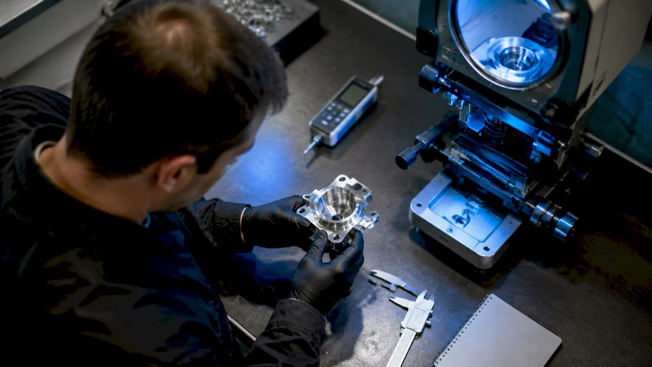
DFM in machining is the systematic practice of shaping part designs so that CNC milling, turning, wire EDM, and related processes can produce them efficiently, accurately, and at the lowest viable cost. The discipline covers geometry, feature sizing, surface finish, tolerance specification, material selection, and fixturing strategy. Each of those variables directly affects cycle time, scrap rate, and first-pass yield.
The engineering mindset behind DFM is not a cost negotiation checklist. It is a structured way of asking, at every design decision point, whether the shop floor can actually execute what the drawing demands. A pocket with a 0.5mm internal radius looks clean in CAD but forces the use of a small, fragile end mill running at low feed rates. That single feature can double the cycle time for an otherwise straightforward part.
Effective DFM shortens time to market and stabilizes product quality by embedding manufacturing knowledge into design early. For OEMs producing high volumes, that stability translates directly into predictable unit costs and on-time delivery. The importance of DFM in machining grows with part complexity, tighter tolerances, and higher production quantities.
What are the fundamental DFM concepts and best practices in machining?
Core DFM concepts in machining center on five areas: feature geometry, internal radii, surface finish, tolerance specification, and tool accessibility. Getting these right at the design stage eliminates the most common sources of machining inefficiency.
Feature geometry and internal radii are the first place to look. Increasing an internal corner radius from 1mm to 3mm can significantly reduce cycle time by enabling larger, more rigid tooling that operates at higher feed rates. Larger, stiffer tools reduce vibration, allow faster cuts, and last longer between changes. The geometry change costs nothing on the drawing and saves real money on the floor.
Pro Tip: When specifying internal radii, default to a radius at least 1.5x the depth of the pocket. This ratio allows standard end mills to reach full depth without deflection, cutting cycle time and improving surface finish in a single decision.
Tool accessibility is the constraint most often ignored at the design stage. All features must be reachable from a limited number of machine faces in CNC machining, and designs that require more than four or five setups multiply fixturing time and introduce alignment error. Designing parts so that all critical features are accessible from two or three faces is one of the highest-leverage DFM techniques available.
Tolerance specification is where over-engineering does the most damage. Over-specifying tolerances increases machining time, scrap, and inspection cost without improving product performance unless the feature is functionally critical. Apply tight tolerances only where fit, function, or safety demands them.
Top DFM best practices for machined parts:
- Maximize internal radii to match standard tooling sizes
- Minimize the number of part setups by consolidating features on accessible faces
- Specify surface finish only as tight as function requires
- Avoid deep, narrow slots that require fragile tooling
- Use standard hole sizes and thread forms to eliminate custom tooling
- Align datum surfaces with functional reference points used in inspection
How does DFM differ from DFA and DFMA in manufacturing?
DFM focuses on part feasibility and piece cost; DFA focuses on assembly time and complexity; DFMA unites both to optimize total product cost. Understanding the scope of each discipline prevents engineers from applying the wrong lens to a given problem.
DFA asks questions like: How many fasteners does this assembly require? Can components be inserted from a single direction? Can parts be made self-locating to reduce assembly time? These questions are irrelevant to a standalone machined component but become critical when that component is one of thirty parts in a subassembly.
DFMA combines both disciplines and is most valuable during the concept phase of a new product, when design freedom is highest and the cost of changes is lowest. For machining-focused teams, DFM is the primary tool, with DFA becoming relevant when machined parts feed into larger assemblies.
| Discipline | Primary focus | Key question addressed |
|---|---|---|
| DFM | Part feasibility and piece cost | Can this part be machined efficiently and economically? |
| DFA | Assembly time and complexity | Can this assembly be put together faster with fewer steps? |
| DFMA | Total product cost optimization | How do design choices affect both manufacturing and assembly cost? |
The practical implication for machining teams is that DFM decisions made in isolation can create DFA problems downstream. A part optimized for CNC turning may require a complex fixture in final assembly. Cross-functional review that includes both manufacturing and assembly engineers catches these conflicts before they become production problems.
What obstacles do engineers face when implementing DFM in machining?
The most common DFM failure mode is not ignorance of the principles. It is the organizational gap between design and production. DFM requires active collaboration between designers, manufacturing engineers, and stakeholders) to align specifications with processes, materials, and equipment. When those groups work in sequence rather than in parallel, DFM becomes a review exercise instead of a design input.
Specific obstacles that manufacturing engineers encounter most often:
- Tolerance over-specification: Designers apply tight tolerances across entire drawings rather than targeting critical features, driving up inspection and scrap costs
- Ignored fixturing constraints: Features are positioned without considering how the part will be held during machining, leading to vibration, chatter, and poor surface finish
- Tooling blind spots: Internal features are designed without checking whether standard tooling can reach them, forcing custom tool orders and longer lead times
- Late-stage redesigns: DFM reviews scheduled after detailed design is complete find problems that require significant rework, erasing the cost savings DFM was meant to deliver
- GD&T misalignment: Geometric Dimensioning and Tolerancing callouts reference datums that do not match the functional surfaces used for fixturing or inspection
Pro Tip: Align GD&T datum references with the actual clamping surfaces used on the machine and the measurement surfaces used in inspection. When the datum on the drawing matches the datum on the fixture and the CMM setup, rework and inspection confusion drop sharply.
The remedy for most of these obstacles is the same: bring manufacturing engineers into the design process at the concept stage, not the release stage. Simulation tools in Autodesk Fusion and CAM software like Mastercam allow designers to validate tool paths and fixturing strategies before committing to a final design. That validation loop is where the real cost savings from DFM are captured. For guidance on managing complex part geometry through these challenges, the strategies apply directly to DFM implementation.
How to apply DFM techniques practically in machining workflows
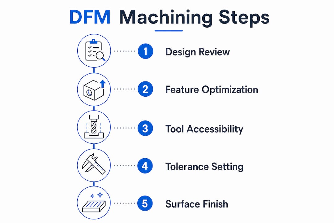
Applying DFM in a real machining workflow requires a structured sequence, not a single review gate. The following steps reflect how high-performing manufacturing teams integrate DFM from concept through production release.
-
Define the process first. Before finalizing geometry, select the machining process: CNC milling, turning, wire EDM, or a combination. Each process has specific constraints on feature geometry, minimum wall thickness, and achievable tolerances. Designing to the process from the start eliminates the most expensive category of late-stage changes.
-
Run a DFM check at concept design. Review the concept model against a DFM checklist covering internal radii, tool access, setup count, and tolerance distribution. This review should take less than an hour and can prevent weeks of redesign later.
-
Validate with CAM simulation. Load the design into CAM software and simulate tool paths. Collisions, unreachable features, and excessive setup changes appear immediately. Autodesk Fusion’s integrated CAM environment allows this validation without leaving the design workspace.
-
Engage the production team before detail design is locked. Share the concept model with the machinists or contract manufacturer who will produce the part. Their feedback on fixturing, tooling, and cycle time is the most direct form of DFM input available. Early involvement of manufacturing considerations including fixturing and inspection alignment leads to more repeatable production and higher yields.
-
Apply tolerances functionally, not uniformly. Review every tolerance callout and ask whether the function of the part actually requires it. Tighten only the features that drive fit, function, or safety. Leave the rest at standard machining capability.
-
Document DFM decisions for future programs. Record which design choices reduced cycle time or improved yield. That knowledge base becomes a precision part design resource for the next program, compounding the efficiency gains over time.
DFM is a business strategy disguised as engineering, with every decision judged by its impact on cost, quality, and schedule. Teams that treat it as a structured workflow rather than a checklist see the largest gains in first-pass yield and cycle time reduction.
Key takeaways
DFM in machining delivers its greatest value when manufacturing constraints are treated as design inputs, not post-design filters.
| Point | Details |
|---|---|
| Early DFM prevents costly redesigns | Late-stage design changes cost 10x to 100x more than corrections made during concept design. |
| Internal radii drive cycle time | Increasing corner radii to match standard tooling sizes reduces cycle time and tool wear substantially. |
| Tolerance discipline reduces scrap | Apply tight tolerances only to functionally critical features to cut inspection time and scrap rates. |
| Cross-functional collaboration is required | Designers and manufacturing engineers must work in parallel, not in sequence, for DFM to function. |
| DFM differs from DFA and DFMA | DFM targets piece cost and feasibility; DFA targets assembly; DFMA addresses both for total cost optimization. |
Why DFM is the discipline most machining teams underuse
I have reviewed hundreds of part drawings over the years, and the pattern is consistent: the most expensive machining problems trace back to decisions made in the first 20% of the design process. A pocket that is 0.2mm too narrow for a standard end mill. A datum that references a surface no fixture can hold. A tolerance of ±0.001" applied to a feature that functions perfectly at ±0.005". None of these are complex problems. They are all fixable in five minutes at the concept stage and in five days at the production stage.
What I find most underappreciated is that DFM is not primarily about reducing cost. It is about reducing variability. A part designed with DFM principles produces consistent results across thousands of cycles because the process is not fighting the geometry. That consistency is what separates a 98% yield from an 85% yield at high volume, and the difference compounds fast when you are producing millions of parts annually.
The emerging integration of AI-assisted DFM tools into CAD platforms is changing the speed of this feedback loop. Automated geometry checks that flag non-standard radii, inaccessible features, and tolerance stack-ups in real time are already available in platforms like Autodesk Fusion. Teams that adopt these tools early will close the gap between design intent and production reality faster than those relying on manual review alone.
My strongest advice: stop treating DFM as a gate at the end of design and start treating it as a constraint at the beginning. The engineers who do that consistently produce better parts, faster, at lower cost. That is not a theory. It is what the data from every late-stage redesign confirms.
— Andrew
How Machiningtechllc supports DFM-driven production
Machiningtechllc brings over 40 years of precision machining experience to OEMs and industrial manufacturers who need DFM principles applied at production scale. Operating from a 70,000 square foot facility in Webster, Massachusetts, the team works with clients from prototype through full-scale production, offering feedback on part geometry, tolerances, and fixturing strategy before the first part is cut.
For manufacturers targeting faster time to market and lower piece costs, Machiningtechllc’s contract machining services are built around exactly the kind of design-to-production alignment that DFM demands. With Hydromat systems, CNC milling, turning, and wire EDM under one roof, the team produces over 20 million parts annually across aerospace, defense, and industrial machinery. Explore precision parts manufacturing capabilities to see how DFM expertise translates into measurable production outcomes.
FAQ
What is DFM in machining?
DFM in machining stands for Design for Manufacturability. It is the practice of designing parts so that CNC machining and related processes can produce them efficiently, at consistent quality, and at the lowest viable cost.
How does DFM reduce manufacturing cost?
DFM reduces cost by eliminating features that require specialized tooling, minimizing setup count, and applying tight tolerances only where function demands them. Late redesigns cost 10x to 100x more than corrections made during concept design, making early DFM the highest-return investment in the product development cycle.
What is the difference between DFM and DFMA?
DFM focuses on making individual parts feasible and cost-efficient to machine. DFMA combines DFM with Design for Assembly (DFA) to optimize both piece cost and assembly time, addressing total product cost rather than individual component cost.
Which design features most affect CNC machining DFM?
Internal corner radii, feature accessibility from machine faces, tolerance specification, and surface finish requirements are the four design variables with the greatest impact on CNC machining cycle time, scrap rate, and tooling cost.
When should DFM be applied in the design process?
DFM delivers the most value when applied at the concept design stage, before geometry is locked. Collaboration between designers and manufacturing engineers) at this stage prevents the fixturing, tooling, and tolerance problems that drive costly late-stage redesigns.
Recommended
- Machinability of materials guide for precision 2026 | Machining Technologies
- The Role of CAD/CAM in Machining: 2026 Guide | Machining Technologies
- Master Precision Machining Workflow for Firearms Components | Machining Technologies
- Custom vs standard machining: choosing the right fit | Machining Technologies