

TL;DR:
- Proper tolerance analysis and documentation are critical to ensure high-volume manufacturing consistency.
- Early cross-functional reviews help identify design errors before costly tooling and production.
- Understanding real-world error sources beyond mathematical models improves part reliability and reduces rework.
A single tolerance set 0.002 inches too loose on a bore diameter can cascade into hundreds of failed assemblies before anyone pinpoints the root cause. In high-volume machining environments, where a single shift can push thousands of parts through the line, that kind of oversight is not just frustrating — it is expensive. This guide walks manufacturing engineers and procurement specialists through a structured, practical approach to precision part design: from gathering functional requirements and selecting materials, through tolerance analysis, drawing release, and final validation. Follow this sequence and you will dramatically reduce rework, scrap, and the painful back-and-forth that eats into your program margins.
Table of Contents
- Gathering requirements and preparing for design
- Step-by-step workflow: designing precision parts
- Tolerance analysis and error propagation
- Validation, drawing release, and troubleshooting
- A precision engineer’s perspective: What most guides miss about reliable part design
- Streamline precision part design and manufacturing with expert support
- Frequently asked questions
Key Takeaways
| Point | Details |
|---|---|
| Preparation drives success | Gathering requirements and cross-functional input early avoids costly corrections later. |
| Structured workflow matters | A disciplined, stepwise process ensures design intent is preserved through machining. |
| Master tolerance analysis | Understanding and modeling error propagation is the backbone of consistent high-volume results. |
| Validate before releasing | Final design checks and cross-functional review are the surest ways to minimize downstream defects. |
Gathering requirements and preparing for design
Good part design does not start in CAD. It starts in a conference room, a Teams call, or an email thread where every stakeholder agrees on what success looks like. Rushing past this phase is the single most common reason designs require costly revisions after tooling is cut.
Start by documenting every functional requirement in writing. This means critical dimensions, load-bearing specs, environmental exposure, regulatory constraints (think AS9100 for aerospace or MIL-SPEC for defense), and expected service life. Do not assume your CAD team and your procurement lead share the same mental model of a “tight tolerance.”
Material selection deserves equal attention. Define expected performance criteria upfront:
- Tensile and yield strength requirements based on loading conditions
- Wear resistance for sliding or rotating contact surfaces
- Corrosion resistance for harsh or wet environments
- Machinability rating relative to your planned production volume
- Cost targets that align with your per-unit budget
For tolerance planning, note that tolerance analysis propagates random deviations through dimension chains — this is a design methodology, not just arithmetic on a drawing. Understanding that early shapes how you assign tolerances to functional vs. non-functional features.
The table below summarizes common tolerance grades matched to typical surface finish targets:
| Tolerance grade | Typical IT grade | Surface finish Ra (µin) | Typical application |
|---|---|---|---|
| Coarse | IT12–IT14 | 125–250 | Non-mating structural features |
| Medium | IT9–IT11 | 63–125 | General machined interfaces |
| Fine | IT6–IT8 | 16–63 | Precision fits, bearing bores |
| Ultra-fine | IT4–IT5 | 4–16 | Gauging, lapping surfaces |
Visit our detailed breakdown of precision part manufacturing strategies for a deeper look at how these grades map to production processes. You can also explore how we balance quality and throughput in part manufacturing at scale.
Pro Tip: Run a cross-functional design review with engineering, procurement, and quality before any CAD work begins. These early reviews act as error traps, catching misaligned expectations when changes are still cheap.
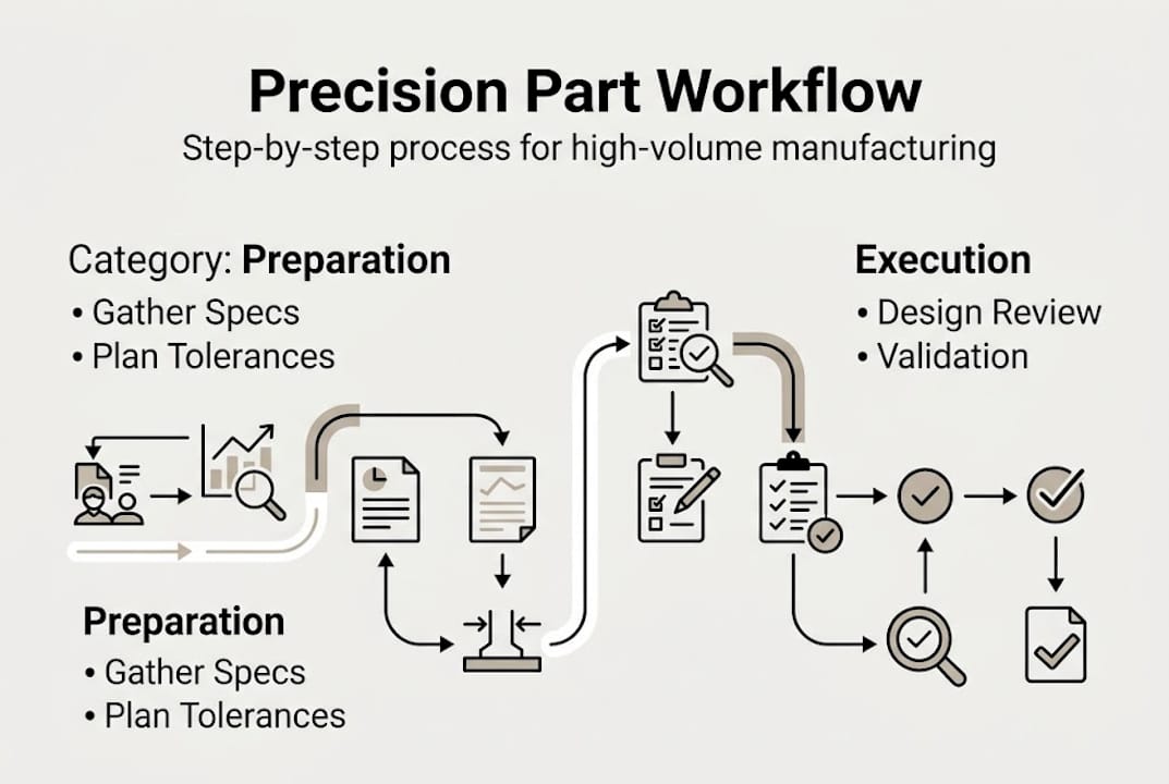
Step-by-step workflow: designing precision parts
With requirements locked in, the actual design workflow should follow a predictable sequence. Skipping steps or running them in parallel without proper handoffs is where most teams introduce the errors they spend weeks chasing later.
- Build detailed CAD geometry. Fully dimension every feature. Avoid reference dimensions on drawings that are not controlled — they create ambiguity during inspection.
- Apply GD&T (geometric dimensioning and tolerancing). Assign datum reference frames before tolerancing individual features. This ensures your inspector and your machinist share the same measurement baseline.
- Run a tolerance stack-up analysis. Identify the worst-case assembly condition and confirm your design still functions at the stack limits.
- Simulate for manufacturability. Check tool access, fixturing clearance, and feature-to-feature interference using your CAD environment’s simulation tools.
- Internal design review. Circulate the model and preliminary drawing to your cross-functional team before freezing the design.
- Release to manufacturing with a revision-controlled drawing. Nothing leaves the engineering team without a documented revision and date.
Research confirms that systematic errors resist reduction through the same methods used for random errors, which means your experimental coefficient-estimation plan matters as much as your nominal geometry. Using a least-squares approach over finite-difference methods improves coefficient accuracy and gives you a more realistic picture of real-world deviation.
The table below compares two common tolerance stack-up analysis approaches:
| Method | Best for | Limitation |
|---|---|---|
| Worst-case analysis | Safety-critical assemblies | Overly conservative; increases cost |
| RSS (root sum square) | High-volume assemblies with random variation | Assumes normal distribution |
| Monte Carlo simulation | Complex multi-part assemblies | Requires statistical input data |
Our documented precision machining workflow for high-precision components shows how this sequenced approach translates from the design office to the shop floor. For industry-specific guidance, see our aerospace machining best practices for tighter regulatory environments.
Pro Tip: Document every design assumption — material property source, load case justification, tolerance rationale — in a design record file. When a part fails inspection six months from now, that file is the fastest path to root cause.
Tolerance analysis and error propagation
Tolerance analysis is where design theory meets manufacturing reality. Dimension chains are sequences of part and assembly dimensions that together determine a critical gap or fit. When you change one link in that chain, every downstream dimension feels it.

Random errors are the part-to-part variation you expect from any real machining process. They follow statistical distributions and can be modeled with tools like Monte Carlo simulation. Systematic errors are different — they are consistent, repeatable offsets that show up the same way every cycle. A worn tool, a thermal gradient in a machine spindle, a fixture that consistently pushes the part 0.0005 inches in one direction. These do not average out.
Top tolerance analysis methods used in precision manufacturing:
- Worst-case analysis: Guarantees function regardless of variation, but often drives unnecessary cost
- RSS analysis: Statistically balances tolerance allocation across a dimension chain
- Monte Carlo simulation: Models complex assemblies with thousands of simulated build iterations
- Sensitivity analysis: Identifies which dimensions contribute most to assembly variation
Dimensional chains propagate random deviations and systematic errors interact differently within those chains, which means advanced coefficient estimation does not always cancel out a persistent systematic offset. Plan your experimental design accordingly.
Critical note: Numerical models predict ideal behavior. They cannot fully account for machine-specific thermal drift, operator-driven process variation, or cutting tool degradation mid-run. Always validate model predictions against first-article inspection data before committing to full production.
For in-depth guidance on applying these methods to flight-critical and defense components, review our tolerance best practices for aerospace resources.
Key insight: Switching from finite-difference to a least-squares experimental plan for coefficient estimation can meaningfully improve prediction accuracy for systematic error sources — a practical gain when your production run is measured in millions of parts.
Validation, drawing release, and troubleshooting
A design is only as good as its validation process. Completing CAD geometry is not the finish line. The finish line is a fully reviewed, revision-controlled drawing that your machining team can execute without calling an engineer for clarification.
Use this stepwise validation checklist before releasing any drawing:
- Dimensional review: Confirm all critical dimensions are explicitly called out and match the design intent from your requirements document.
- Tolerance stack verification: Run the final stack-up analysis against your assembly fit requirements. Check worst-case and RSS conditions.
- DFM (design for manufacturability) check: Confirm that tool access exists for every machined feature, wall thicknesses are adequate, and hole depth-to-diameter ratios are within standard machine capability.
- GD&T audit: Verify datum reference frames are complete, all controlled features reference the correct datum, and no conflicting callouts exist.
- Peer review: Have at least one engineer who did not create the drawing review it cold.
Drawing best practices that prevent downstream errors:
- Annotate all critical features with explicit inspection callouts, not just tolerances
- Use datum referencing consistently across every related drawing in an assembly
- Implement revision control with a clear change history block — no informal “latest version” files
- Call out surface finish on every functional face, not just critical bores
- Flag first-article inspection (FAI) requirements directly on the drawing
Tolerance analysis prior to release is the most effective lever for reducing errors that propagate into full production. Catching a tolerance conflict on a drawing costs an hour of engineering time. Catching it after 10,000 parts are made costs far more.
Pro Tip: Pre-release peer review statistically catches 60 to 70 percent of preventable drawing errors. Build it into your release gate, not as a courtesy check but as a mandatory hold point.
For sourcing support that maps to your validated design specs, explore our precision parts sourcing tips for aerospace and defense programs.
A precision engineer’s perspective: What most guides miss about reliable part design
Every step-by-step guide eventually ends. The hard part is what happens when the process meets reality.
Here is what years of high-volume precision machining have taught us: a perfect digital design can still fail when process selection is wrong or shop-floor practices are misaligned with design assumptions. Engineers who obsess over theoretical tolerance models but never walk the production floor are setting themselves up for costly surprises. The real gains come from understanding where your actual error sources live — in the spindle, in the fixture, in the material batch — not just in the math.
Upstream communication matters more than any software update. A culture where design engineers talk to machinists before freezing tolerances catches problems that no simulation will surface. The best teams we work with treat the drawing release as a conversation, not a handoff.
“Documentation and structured discussion will save your program more money than any new CAD license. The tool matters less than the discipline around it.”
Precision is a team sport. Whether you are designing for firearms accuracy — where you can see how firearm engineering for accuracy demands extreme process discipline — or for aerospace structure, the lesson is the same: align your people before you align your tolerances.
Streamline precision part design and manufacturing with expert support
Putting this process into practice at scale requires the right manufacturing partner. At Machining Technologies LLC, we have been producing complex, high-tolerance components since 1985, with a 70,000 square foot facility and the capacity to deliver over 20 million parts annually across aerospace, defense, and industrial programs.

Our team works directly with engineering and procurement teams to review designs before production begins, flagging DFM issues, tolerance conflicts, and material concerns early. Explore our full range of precision parts manufacturing services to see how we support OEM programs from prototype through high-volume production. For contract manufacturing at scale, our OEM contract machining capabilities are built for demanding, high-mix programs. And for complex turned and milled components, our CNC milling and turning services deliver the repeatability your program requires.
Frequently asked questions
What is the most important step in precision part design for high-volume machining?
Robust tolerance analysis combined with documented design assumptions is most critical. These directly govern whether your part will repeat consistently across a high-volume production run. As research confirms, tolerance analysis controls the deviations that determine production quality.
How do systematic and random errors differ in part design?
Random errors vary from part to part and can be managed statistically, while systematic errors are repeatable offsets that persist across every cycle. Systematic errors remain a design risk even after random error models are refined.
Why is early cross-functional review important?
Early reviews surface manufacturing risks and specification conflicts when they are still inexpensive to fix. Cross-functional reviews trap errors that would otherwise propagate all the way to production.
What tools are essential for effective tolerance analysis?
CAD platforms with GD&T support, Monte Carlo simulation software, and tolerance stack-up worksheets are the core toolkit for most high-volume programs. The right method depends on assembly complexity and risk level.
How can I validate a drawing before sending it to manufacturing?
Work through a structured checklist: dimensional review, tolerance stack verification, DFM assessment, GD&T audit, and a mandatory peer review before release. Validation checks before release are the most cost-effective way to prevent production errors.
Recommended
- Complex part manufacturing: precision strategies 2026 | Machining Technologies
- Optimize high-volume machining workflow: aerospace precision | Machining Technologies
- Precision Parts Manufacturing: Maximizing Quality and Throughput | Machining Technologies
- Master Precision Machining Workflow for Firearms Components | Machining Technologies