

TL;DR:
- Most machining cycle time estimates are incomplete because they focus solely on cutting time, ignoring significant non-cutting overhead. Accurately assessing total cycle time requires breaking down and measuring each element, such as tool changes, rapid moves, and part handling, to improve throughput and profitability. Managing and tracking non-cutting time is crucial for continuous process improvement, reliable quoting, and strategic capital investments.
Most engineers can write a feed rate formula in their sleep. Where things get complicated is when that formula becomes the entire cycle time estimate. Cutting time is only one part of the equation, and treating it as the whole story leads to underpriced quotes, blown schedules, and process improvement efforts that target the wrong variables. Cutting-time equations model only tool-engagement time, but total machining cycle time must include every non-cutting element from rapid moves and tool changes to probing, dwell, and part handling. Getting this right is the difference between hitting your throughput targets and constantly chasing them.
Table of Contents
- What actually determines machining cycle time?
- How to estimate machining cycle time step by step
- Why cutting time alone misleads: Costs, quoting, and KPIs
- Best practices for reducing machining cycle time
- The overlooked ROI of mastering cycle time breakdown
- Unlock faster, more precise production with expert cycle time strategies
- Frequently asked questions
Key Takeaways
| Point | Details |
|---|---|
| Cutting vs. total cycle time | Cycle time includes both cutting and non-cutting events; ignoring overhead leads to errors. |
| Stepwise estimation method | Calculate per-operation times, add overhead, and always include contingency for accuracy. |
| Non-cutting overhead matters | Short-cycle parts and complex toolpaths are heavily influenced by events outside of cutting. |
| Quoting pitfalls | Basing quotes on cutting time alone typically underestimates costs by 15–50%. |
| Optimize both time types | Cycle time can be cut fastest by attacking both tool-engagement and all operational overheads. |
What actually determines machining cycle time?
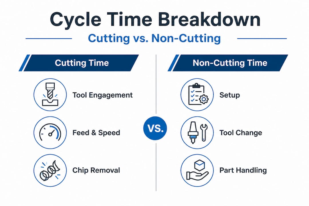
Cycle time is made up of two fundamentally different categories of time, and confusing one for the other is one of the most common and costly errors in precision machining environments.
Cutting time covers actual tool engagement: the time spent removing material at programmed feeds and speeds, across a defined path length and engagement strategy. Non-cutting overhead is everything else. Rapid positioning between features, tool changes at the ATC, approach and retract moves, probing cycles, dwell commands, part loading and unloading, and any machine state transitions between operations. Per CNC Cycle Time Formulas, total machining cycle time must account for all non-cutting elements, not just tool-engagement time.
Here is a side-by-side look at the two categories and how their time contributions are typically sourced:
| Element | Category | Time Source |
|---|---|---|
| Milling, turning, drilling passes | Cutting | Feed rate, path length, depth of cut |
| Rapid moves between features | Non-cutting | Machine rapid rate, distance |
| ATC tool change | Non-cutting | Machine spec (typically 3–8 sec each) |
| Approach and retract moves | Non-cutting | Programmed feed, clearance distance |
| In-process probing | Non-cutting | Probe cycle time, number of points |
| Part load/unload (manual or robotic) | Non-cutting | Handling method, fixture complexity |
| Dwell commands | Non-cutting | Programmed dwell value |
| Spindle acceleration/deceleration | Non-cutting | Machine spindle spec |
On a long-cycle part with hours of 5-axis contouring, non-cutting time may represent only 10 to 15 percent of the total. But for short-cycle, high-volume parts, such as a turned component with six tool changes and a probing step, non-cutting overhead can easily consume 40 to 60 percent of actual cycle time. Understanding the cycle time benefits for high-volume parts starts with recognizing this ratio and managing it deliberately.
Key contributors to total cycle time in a typical CNC operation include:
- Cutting time per operation (milling, turning, drilling, boring, reaming)
- Rapid traverse time between operations or features
- Tool change time multiplied by number of changes in the program
- Approach/retract time at programmed feed to and from cutting depth
- Probing and gauging cycles between operations or at end of program
- Part handling time including fixture change, manual orientation, or robotic transfer
- Dwell and machine state transitions at spindle start, coolant on/off, pallet change
For precision strategies on complex parts, mapping each of these elements separately is essential before any optimization work begins.
Pro Tip: Always document what percentage of your cycle is non-cutting time. This breakdown is often where the most actionable optimization opportunity is hiding, and most shops never formally track it.
How to estimate machining cycle time step by step
Clarifying the components is only half the battle. Accurate estimation takes a disciplined workflow, and skipping steps here is exactly where projects go over budget or under schedule.
A practical cycle-time estimating workflow, per How to Calculate Machining Time, requires calculating per-operation cutting time first, then summing all overheads, rather than relying on a single global “cutting time equals cycle time” assumption. Here is the recommended sequence:
- Break the program into individual operations. List every distinct machining operation in program order: rough turning, finish turning, drilling, milling, threading, and so on.
- Calculate cutting time for each operation. Use the appropriate formula for each operation type. For turning: T = L / (f × n), where L is length of cut, f is feed per revolution, and n is spindle speed in RPM. For milling: T = L / Vf, where Vf is feed rate in inches or millimeters per minute.
- Sum all tool changes. Multiply the number of tool changes by the actual ATC time listed in your machine specification. Many engineers use a round number like 5 seconds without checking the actual spec. That error compounds across millions of parts.
- Add all rapid move times. Calculate distance between operations and divide by your machine’s rapid traverse rate. For a Fanuc-controlled machining center, this might be 1,400 inches per minute, but actual effective rapids during 3D moves are lower due to acceleration ramps.
- Account for approach, retract, and dwell. These are programmed in the NC code but often excluded from hand calculations. Pull them from your CAM simulation output.
- Add inspection and probing time. Each probing point adds measurable time. A 10-point probing routine at 200 mm per minute takes longer than most people estimate when you include orientation moves.
- Add part handling and setup transitions. Loading time, clamping, deburring between ops, and pallet changes all belong in the total cycle time.
The following sample table illustrates how this plays out for a representative turned and milled component:
| Operation | Calculated cutting time | Overhead added | Measured cycle time |
|---|---|---|---|
| Rough turning OD | 42 sec | 8 sec (approach/retract) | 50 sec |
| Finish turning OD | 18 sec | 8 sec | 26 sec |
| Face grooving | 11 sec | 5 sec tool change + 6 sec | 22 sec |
| Cross-drilling (4 holes) | 28 sec | 10 sec tool change + 12 sec rapids | 50 sec |
| In-process probing | 0 sec cutting | 22 sec | 22 sec |
| Part load/unload | 0 sec cutting | 30 sec | 30 sec |
| Total | 99 sec | 101 sec | 200 sec |
That is a two-to-one ratio between cutting and non-cutting time on a relatively simple part. Short-cycle parts are disproportionately impacted by non-cutting overhead, and this example shows exactly why measured cycle time can be nearly double the calculated cutting time. Reviewing your machining workflow steps through this lens will reveal the gaps your current estimating method is missing.

For high-volume manufacturing examples at scale, even a 3-second reduction in non-cutting overhead per part translates to meaningful throughput gains across tens of thousands of cycles per year.
Pro Tip: Add a contingency buffer of 15 to 50 percent to your cycle time quote, scaled to program complexity. Multi-tool, multi-step programs with close tolerances consistently run higher than calculated time, especially on first article runs and during early production ramp-up.
Why cutting time alone misleads: Costs, quoting, and KPIs
With estimation methods in mind, it is also essential to understand the practical risks when cutting time is mistaken for total cycle time.
Quoting solely from cutting time can systematically underprice jobs significantly. Manual T = L/F style estimates can be off by 15 to 30 percent for simple operations and diverge by 30 to 50 percent for complex 3D toolpaths with multiple tool changes and acceleration ramps. That variance does not stay in the shop. It flows directly into margin erosion, missed delivery windows, and frustrated customers.
The main problems that arise from conflating cutting time with cycle time include:
- Underpriced quotes that become unprofitable as actual shop floor time exceeds the estimate
- Missed delivery commitments when scheduled hours per part are understated
- Inaccurate OEE and throughput KPIs built on an ideal cycle time that does not reflect real machine behavior
- Distorted process improvement efforts where engineers optimize the wrong variable
- Inaccurate capacity planning leading to overcommitted machines or underutilized cells
- Incorrect labor and overhead absorption in cost accounting models
“For OEM-style performance measurement, using OEE-style metrics requires care with the ‘ideal cycle time’ reference: in mixed-job or non-dedicated scenarios, an assumed ideal cycle time can distort performance comparisons across different parts and programs.”
This is especially significant for manufacturing engineers responsible for reporting OEE or similar metrics. When your ideal cycle time reference is built from cutting time alone, your OEE score looks better than it really is. When you eventually measure actual cycle time and correct the reference, performance appears to drop overnight even though nothing in the process changed. That kind of metric instability undermines trust in the data and slows decision-making at every level.
Buyers and procurement managers face an equally significant risk. If a supplier’s quote is built from cutting time only, the initial price looks attractive. But as the job runs, late deliveries and re-quoting requests follow. Evaluating machining equipment efficiency gains at the supplier level requires asking how they estimate cycle time, not just what rate they charge.
For engineers, the actionable step is to require actual timed data from production runs, not just calculated cutting time from the program. For buyers, it means asking suppliers to document their cycle time estimation methodology before accepting a quote.
Best practices for reducing machining cycle time
Having seen the pitfalls of poor estimation, let’s turn to the specific levers that deliver faster, more precise production.
Cycle-time improvement for high-precision machining is most effectively achieved by reducing non-cutting time and by optimizing feed and speed strategy alongside toolpath interpolation. Blanket speed increases without attention to engagement strategy often produce diminishing returns or accelerated tool wear that erases the time savings.
Practical strategies that consistently deliver results include:
- Optimize ATC sequence. Reorder tools in the magazine to minimize travel distance during automatic tool changes. On high-mix jobs, this alone can reduce ATC time by 15 to 25 percent.
- Minimize rapid move distances. Review your CAM output for inefficient rapid paths between features. Repositioning your workpiece datum or adjusting clearance planes can cut cumulative rapid time significantly.
- Reduce approach and retract distances. Tighten clearance values in your CAM settings. Many programmers use conservative defaults that add seconds to every operation.
- Streamline part handling. Evaluate whether fixture changes, deburring between operations, or manual reorientations can be automated or combined. On optimizing aerospace machining workflows, part handling improvements frequently deliver larger gains than spindle speed increases.
- Maintain optimal feeds and speeds. Running at correct cutting parameters reduces cycle time and extends tool life simultaneously. Underfeeding wastes time; overfeeding risks rework.
- Address peck drilling efficiency. Peck drilling cycles add significant non-cutting time through retract and re-entry moves. Evaluate chip-breaking cycles or through-coolant tooling as alternatives where hole depth permits.
- Use simulation before runtime changes. Digital simulation catches collisions and efficiency issues before they become production problems. Test cycle time changes in CAM before committing to a new program revision.
For maximizing quality and throughput simultaneously, the discipline of tracking non-cutting time separately from cutting time is what separates shops that improve consistently from those that plateau after initial optimization gains.
Pro Tip: Use your CAM software’s machine simulation output to extract a preliminary non-cutting time estimate before the part ever runs. Compare it to your actual timed run data and use that gap to guide where you focus next.
The overlooked ROI of mastering cycle time breakdown
Now, having worked through estimation methods and best practices, consider this: what if your greatest efficiency gains have nothing to do with buying faster equipment?
Most capital budgeting discussions in manufacturing center on machine capability, spindle speed, control systems, and automation hardware. These are real improvements, but they are expensive and slow to deploy. What we have seen repeatedly is that two facilities with essentially identical equipment produce very different output rates, and the differentiator is not the hardware. It is whether the engineering team actively tracks and manages the split between cutting and non-cutting time.
The plant that distinguishes cutting time from overhead can see exactly where its cycle time budget goes. It can run structured improvement cycles, measure the impact of each change, and compound those gains quarter over quarter. The plant that treats cycle time as a single opaque number keeps chasing throughput without a clear theory of where the time is going.
This plays out in capital budgeting too. When you know that 45 percent of your cycle time is non-cutting overhead, you can calculate the ROI of a faster ATC, a robotic part handler, or a revised toolpath strategy with real numbers. When you treat cycle time as a black box, you make capital decisions based on vendor claims rather than your own process data.
The shops that consistently outperform on throughput per dollar of capital deployed are not always the ones with the newest machines. They are the ones with the deepest understanding of where their time actually goes. Staying current on 2026 machining trends matters, but it matters more when you have a baseline that tells you which trends are actually relevant to your specific cycle time profile.
Encourage your team to track non-cutting time as a formal KPI. Review it on a regular cycle, not just when a delivery misses. The discipline of measurement is what creates the data needed for lasting improvement.
Unlock faster, more precise production with expert cycle time strategies
Translating cycle time analysis into real production gains requires both analytical rigor and hands-on machining expertise. That combination is not always easy to build internally, especially under production pressure.

At Machining Technologies LLC, we have been applying structured cycle time methodology across high-volume precision production since 1985, with capacity to produce over 20 million parts annually from our 70,000 square foot facility in Webster, Massachusetts. Our contract machining benefits extend beyond raw capacity to include the kind of estimation transparency and continuous improvement discipline this article describes. Whether you are working through complex part manufacturing with tight tolerances or scaling a high-volume program that needs tighter cycle time control, our team can help you identify exactly where time is being lost and what it will take to recover it. Explore our full range of machining services and reach out to discuss your next project.
Frequently asked questions
What is the difference between machining cycle time and cutting time?
Cutting time only covers the period when the tool is actively engaging material, while total cycle time includes all non-cutting events such as tool changes, rapid moves, probing, and part handling. As CNC Cycle Time Formulas notes, cutting-time equations model only tool-engagement time, so total cycle time requires adding every non-cutting element.
How do you estimate machining cycle times more accurately?
Calculate individual cutting times for each operation using the appropriate formula, then sum all non-cutting overhead including tool changes, rapids, probing, and handling time. Per How to Calculate Machining Time, a per-operation approach rather than a single global estimate produces far more accurate results.
Why does using only cutting time in quotes lead to problems?
Relying on cutting time alone can underprice jobs by 15 to 30 percent on simple operations and by 30 to 50 percent or more on complex multi-tool programs, leading directly to margin erosion and missed delivery commitments.
What are the best ways to reduce total machining cycle time?
Focus on reducing non-cutting overhead first by optimizing ATC sequence, minimizing rapid move distances, and streamlining part handling, then optimize feed and speed alongside toolpath interpolation for cutting time gains.
How does cycle time affect OEE and other production KPIs?
Using an ideal cycle time reference built from cutting time alone inflates OEE scores artificially. As noted in OPE vs OEE in CNC Manufacturing, using an incorrect ideal cycle time in mixed-job scenarios distorts performance comparisons significantly, making normalization to actual measured cycle time a requirement for reliable KPI tracking.
Recommended
- Optimize high-volume machining workflow: aerospace precision | Machining Technologies
- Aerospace machining best practices for precision | Machining Technologies
- Machining Trends 2026: 40% Faster Lead Times + 50% Tool Life | Machining Technologies
- Advanced machining equipment: efficiency gains and ROI | Machining Technologies
- CNC Machining Instructions for Precision Manufacturing Success