

TL;DR:
- Thermal errors contribute up to 70% of machining inaccuracies, impacting aerospace part conformance.
- Calibration strategies include laser interferometry, ballbars, and thermal modeling aligned with global standards like ISO 10791.
- Active compensation techniques can reduce errors by over 85%, ensuring precision in high-stakes aerospace manufacturing.
When thermal errors account for up to 70% of total machining inaccuracies, every degree of temperature drift in your facility becomes a direct threat to part conformance. For aerospace and defense OEMs, that is not an abstract risk. It is the difference between a flight-ready component and a costly nonconformance report. This article breaks down how to classify and address calibration error sources, which global standards govern your supply chain, which measurement technologies deliver the accuracy your programs demand, and how modern compensation strategies can close the accuracy loop to tolerances measured in single-digit microns.
Table of Contents
- Understanding error sources and calibration classification
- Global standards and compliance requirements
- Measurement technologies: Choosing the right approach
- Advanced error compensation strategies for aerospace tolerances
- A fresh look at calibration: What most guides miss
- Machining Technologies: Precision and compliance for aerospace manufacturing
- Frequently asked questions
Key Takeaways
| Point | Details |
|---|---|
| Thermal errors dominate | Thermal effects can account for up to 70% of total machining inaccuracies. |
| Standards-driven calibration | ISO and AS9100/NADCAP set the benchmark for calibration and traceability in aerospace machining. |
| Measurement matters | Laser interferometry and ballbar testing are indispensable for meeting tight tolerances. |
| Error compensation works | Advanced compensation strategies can reduce major error sources by up to 90%. |
| Sensitivity saves cost | Prioritizing high-impact errors allows more efficient calibration schedules and improved uptime. |
Understanding error sources and calibration classification
With the strategic importance established, understanding error types is the first step toward effective calibration.
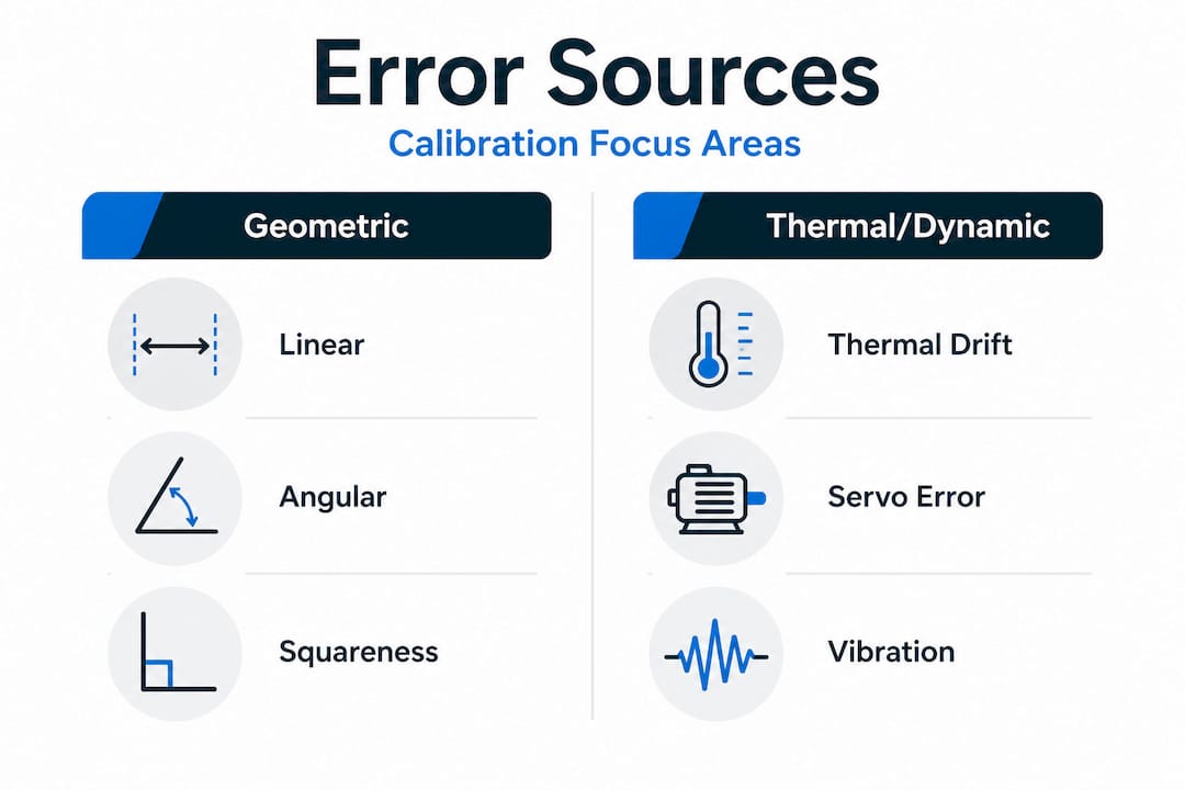
Precision machining errors do not arrive randomly. They follow predictable patterns, and that predictability is exactly what calibration exploits. Machine tool errors classify into three distinct categories: intra-axis errors (deviations occurring within a single axis of motion), inter-axis errors (misalignments between two or more axes), and volumetric errors (the combined spatial deviation at the tool tip across the full working envelope). Each category demands a different calibration response.
Understanding machining tolerance basics is essential before you can interpret what these error categories mean for your specific part geometry. A 5-axis titanium airframe bracket with a 10 µm positional tolerance will respond very differently to inter-axis squareness errors than a simple turned aluminum fitting.
The root causes behind these classifications break into five primary groups:
- Kinematic errors: Geometric imperfections in guideways, spindle bearings, and axis drives that are present even in a cold, static machine
- Thermal errors: Expansion and contraction driven by spindle heat, ambient temperature swings, and coolant temperature variation
- Elastic errors: Deflection under cutting forces, workpiece weight, and fixturing load
- Dynamic errors: Vibration and resonance during high-speed cutting passes
- Motion control errors: Servo lag, encoder resolution limits, and interpolation inaccuracies
“Up to 70% of errors in machining stem from thermal effects. Proactive calibration is the only defense.”
The table below shows how each error type maps to its most effective calibration countermeasure.
| Error type | Primary source | Best calibration method |
|---|---|---|
| Intra-axis (linear) | Guideway wear, encoder error | Laser interferometry |
| Intra-axis (angular) | Bearing preload loss | Autocollimator, laser |
| Inter-axis (squareness) | Assembly misalignment | Ballbar, laser diagonal |
| Volumetric | Combined geometric + thermal | 5-axis compensation model |
| Thermal drift | Spindle/ambient heat | Thermal model, sensor array |
| Dynamic | Resonance, servo lag | Ballbar circularity test |
Recognizing these categories also shapes how you evaluate a contract machining partner. A supplier who only performs periodic ballbar checks is addressing circularity but leaving thermal volumetric drift largely unmanaged. For precision processes in aerospace, that gap is unacceptable on flight-critical hardware.
Global standards and compliance requirements
Once errors are understood, implementing calibration routines that satisfy global standards is the next challenge.
The ISO 10791 series is the backbone of machine tool performance testing for machining centers. ISO 10791 parts 1 through 10 cover geometric accuracy (Part 1), positioning accuracy (Part 2), thermal effects (Part 3), roundness (Part 4), noise (Part 5), multi-axis accuracy (Part 6), and more. Part 6 is particularly critical for aerospace work because it directly governs 4-axis and 5-axis machining center accuracy tests, including angular positioning and tilting axis repeatability.
AS9100 Rev D and NADCAP accreditation layer additional requirements on top of ISO standards. Both frameworks demand full traceability: every calibration measurement must link back to a national or international measurement standard, with documented calibration intervals, uncertainty budgets, and corrective action records. For procurement managers evaluating suppliers, the absence of a NADCAP-compliant calibration program is a disqualifying finding, not a minor gap.
The table below summarizes the key standards and what they govern.
| Standard | Scope | Key calibration requirement |
|---|---|---|
| ISO 10791-1 | Geometric accuracy, linear/rotary axes | Static geometric tests, straightness |
| ISO 10791-2 | Positioning accuracy | Laser interferometry, uncertainty |
| ISO 10791-3 | Thermal effects on accuracy | Thermal drift tests, warm-up protocols |
| ISO 10791-6 | 4/5-axis accuracy | Angular, tilting axis, multi-axis positioning |
| AS9100 Rev D | Quality management for aerospace | Traceable calibration, documented intervals |
| NADCAP | Special process accreditation | Third-party audit, full traceability chain |
Compliance documentation is not a one-time event. It is a living system. Here is a practical sequence for building and maintaining it:
- Identify all machine tools in scope and assign calibration classifications based on part criticality
- Establish calibration intervals using manufacturer recommendations and historical drift data
- Select accredited calibration service providers with national measurement traceability
- Record all calibration results in a controlled document system with revision history
- Define out-of-tolerance response procedures and link them to your nonconformance process
- Schedule internal audits to verify interval compliance before external AS9100 or NADCAP reviews
Reviewing tolerance standards in aerospace alongside your calibration program ensures that your documented intervals actually align with the tolerances your parts require, not just what the machine manufacturer recommends as a general guideline.
Pro Tip: When auditing a potential supplier, always confirm their 5-axis single-setup capability and ask specifically for their ISO 10791-6 test records. A supplier who cannot produce recent multi-axis accuracy data for the specific machine that will run your parts is a compliance risk, regardless of their general certifications.
Measurement technologies: Choosing the right approach
With standards clarified, the right measurement method ensures both compliance and optimal cost control.
Not all measurement tools are created equal, and selecting the wrong one for a given calibration task wastes time, introduces unnecessary uncertainty, or simply misses the error mode you need to catch. Laser interferometers, ballbars, and CMMs each occupy a distinct position in the calibration toolkit, and the best programs use all three strategically.
Laser interferometry measures linear positioning accuracy, straightness, angular errors, and squareness with resolution down to 0.001 µm. It is the reference standard for ISO 10791-2 compliance and the only tool capable of characterizing fine encoder errors across the full axis travel. The limitation is setup time. A full 5-axis machine geometric survey using laser interferometry can take a full shift, which makes it impractical as a daily check.
Ballbar testing measures dynamic circularity errors, servo mismatch, backlash, and stick-slip in a matter of minutes. At ±0.7 µm accuracy, it is not as precise as laser interferometry for absolute positioning, but it is unbeatable for rapid health checks and trending. Most aerospace machine shops run ballbar tests at the start of each production week on critical machines.
Coordinate measuring machines (CMMs) validate the finished part, not the machine itself. They are the final arbiter of conformance and provide the feedback loop that confirms whether your in-process calibration is actually holding tolerances at the part level.
Tracking interferometers (laser trackers) extend volumetric measurement to large workspaces and are increasingly used for 5-axis volumetric compensation mapping.
| Technology | Accuracy | Speed | Cost | Best application |
|---|---|---|---|---|
| Laser interferometer | 0.001 µm | Slow (hours) | High | Full geometric survey, ISO 10791-2 |
| Ballbar | ±0.7 µm | Fast (minutes) | Low | Routine health checks, servo tuning |
| CMM | 0.1–1 µm | Medium | High | Part inspection, final conformance |
| Tracking interferometer | 1–5 µm | Medium | Very high | 5-axis volumetric mapping |
When to use which tool:
- Use laser interferometry for annual geometric surveys and after any major machine repair or crash
- Use ballbar testing for weekly health monitoring and before starting a new production run on critical aerospace parts
- Use CMM inspection at first article, after process changes, and at statistical sampling intervals during production
- Use tracking interferometers when building or updating a volumetric compensation map for a 5-axis machine
Understanding the full range of component machining technologies available helps procurement managers ask the right questions during supplier qualification, rather than accepting vague claims about “tight tolerances” without documented measurement evidence.
Pro Tip: Run a sensitivity analysis on your machine’s error budget before scheduling calibration. Identifying which axes contribute most to volumetric error lets you focus measurement resources where they matter most, often reducing total calibration time by 30 to 40% without sacrificing accuracy assurance.
Advanced error compensation strategies for aerospace tolerances
Closing the accuracy loop means actively correcting errors with the most effective compensation strategies.
Measuring errors is necessary. Compensating for them is where real accuracy gains happen. Modern compensation strategies fall into two broad categories: thermal error compensation and volumetric error compensation. Both have matured significantly, and the results are striking.
Thermal compensation models use temperature sensor arrays mounted at critical machine locations (spindle nose, linear guides, ballscrew nuts, ambient air) to predict thermal displacement in real time. Advanced models using neural network architectures, including CNN-BiLSTM hybrids and Autoformer-based models, reduce spindle thermal errors by up to 90%, dropping deviations from over 12 µm down to less than 2 µm. That is the difference between a part that passes and one that does not.
5-axis volumetric compensation achieves 86% error reduction and characterizes approximately 95% of geometric bias across the working volume. This is accomplished by mapping all 43 geometric error parameters of a 5-axis machine (six per linear axis, six per rotary axis, plus squareness errors), building a compensation table, and feeding real-time offsets to the CNC controller.
“Volumetric compensation models cut 5-axis geometric errors by 86%, characterizing 95% of total geometric bias. Thermal models reduce spindle drift by 90%. Together, they define what aerospace-grade accuracy actually looks like in practice.”
The table below shows representative before and after results from compensation implementation.
| Error location | Before compensation | After compensation | Reduction |
|---|---|---|---|
| Spindle thermal drift (Z) | 12.4 µm | 1.8 µm | 85% |
| X-axis positioning | 8.2 µm | 1.1 µm | 87% |
| Y-axis positioning | 7.6 µm | 1.3 µm | 83% |
| 5-axis volumetric error | 45 µm | 6.3 µm | 86% |
Integrating compensation into an existing workflow does not require a machine replacement. Here is a practical integration sequence:
- Audit current sensor infrastructure and identify gaps in thermal monitoring coverage
- Commission a full geometric survey to establish the baseline compensation map
- Select a compensation software platform compatible with your CNC controller (Siemens, Fanuc, or Heidenhain all support volumetric compensation tables)
- Validate the compensation model using a test part with known geometry before committing production parts
- Schedule model updates at defined intervals or after any event that changes machine thermal behavior (coolant system changes, facility HVAC work, major repairs)
One pitfall many shops fall into is over-relying on hardware fixes, such as adding cooling jackets to ballscrews or redesigning spindle housings, as a substitute for data-driven compensation. Hardware improvements reduce the magnitude of thermal errors but rarely eliminate them. Data-driven compensation addresses the residual error that hardware cannot reach, and it adapts as the machine ages. The combination of both approaches delivers the most robust results for parts quality in precision manufacturing.
For procurement teams evaluating suppliers on complex part precision strategies, asking specifically whether a supplier uses active thermal and volumetric compensation (not just periodic calibration checks) is one of the highest-value qualification questions you can ask.
A fresh look at calibration: What most guides miss
Most calibration guides written for aerospace manufacturing follow the same script: test every geometric parameter, redesign hardware for better thermal stability, and implement full volumetric compensation across all axes. That advice is not wrong. It is just incomplete, and in practice, it can lead procurement teams and engineering managers to over-specify calibration programs in ways that drive up cost and machine downtime without proportional accuracy gains.
The reality is that not all error parameters contribute equally to part inaccuracy. Sensitivity analysis consistently shows that two or three dominant error sources account for the majority of volumetric deviation on any given machine. Calibrating everything with equal intensity is like inspecting every dimension on a complex casting when you know from experience that only four dimensions actually drive fit and function.
Hardware avoidance versus data-driven compensation each carry tradeoffs that matter for tool integrity and setup risk. Indirect probing methods add setup errors and require careful fixture design. Direct measurement approaches risk tool or probe damage in confined workspaces. The right answer is almost always a hybrid: use direct measurement for the high-sensitivity axes and indirect methods for lower-priority parameters.
The most effective calibration programs we have seen are built around risk-stratified intervals. Critical 5-axis machines running titanium structural parts get weekly ballbar checks, monthly thermal model validation, and annual full geometric surveys. Less critical turning centers running aluminum fittings operate on quarterly checks with annual surveys. This tiered approach keeps compliance costs manageable while concentrating calibration intensity exactly where part risk is highest.
“Indirect probes can add setup errors, but direct approaches risk tool damage. Balance is key for procurement.”
For optimizing aerospace workflows, the practical takeaway is this: build your calibration program around your error sensitivity map, not around a generic schedule. The suppliers who do this well deliver more consistent part quality at lower total cost than those who apply maximum calibration intensity uniformly across their entire floor.
Machining Technologies: Precision and compliance for aerospace manufacturing
Bridging advanced calibration theory with real production execution requires a partner who has already built that infrastructure. At Machining Technologies LLC, our 70,000 square foot facility in Webster, Massachusetts operates with calibration programs designed specifically for aerospace and defense OEM requirements, including traceable measurement systems, active thermal compensation on critical CNC platforms, and documented compliance with AS9100 standards.
Whether you need OEM contract machining for high-volume production runs or specialized support for complex part precision solutions on tight-tolerance components, our team brings over 40 years of precision machining experience to every program. We produce more than 20 million parts annually, and our high-volume workflow solutions are built to deliver on-time, every time. Contact us to schedule a calibration audit consultation and see exactly how our processes align with your program requirements.
Frequently asked questions
What are the major sources of calibration error in precision machining?
Primary sources include geometric, thermal, and dynamic errors along with load-induced and motion control deviations, with thermal errors typically being the dominant contributor for high-precision aerospace applications.
How does ISO 10791 apply to multi-axis machining center calibration?
ISO 10791-6 governs 4/5-axis accuracy tests including angular positioning and tilting axis repeatability, providing the specific documentation requirements aerospace suppliers must meet for multi-axis machine compliance.
Which measurement technology offers the highest accuracy for calibration?
Laser interferometry resolves to 0.001 µm, making it the highest-accuracy option for linear positioning calibration and the reference standard for ISO 10791-2 compliance testing.
How much can thermal error compensation improve machining accuracy?
Thermal compensation reduces spindle errors by 80 to 90%, with documented cases showing deviations dropping from over 12 µm to less than 2 µm using advanced neural network compensation models.
Why should procurement managers demand traceable calibration?
AS9100 and NADCAP require traceability to national measurement standards, and suppliers without documented traceability chains cannot reliably demonstrate that their machining processes consistently meet aerospace part tolerances.
Recommended
- Best practices in tolerances for aerospace precision machining | Machining Technologies
- Why tight tolerances matter for aerospace machining | Machining Technologies
- How to verify machined part quality: methods for aerospace OEMs | Machining Technologies
- Precision machining: engineering firearms for accuracy & compliance | Machining Technologies