

TL;DR:
- Proper use of GD&T standards and functional requirements prevents costly tolerance issues.
- Early statistical tolerance analysis helps optimize feature tolerances and reduce costs.
- Collaboration among design, manufacturing, and quality teams ensures successful aerospace tolerance management.
Specifying tolerances in aerospace machining is one of the most consequential decisions a design engineer or procurement manager can make. Get it wrong, and you risk failed first article inspections, expensive rework, or parts that simply cannot be produced at scale. Get it right, and you unlock a supply chain that delivers certifiable, flight-worthy components on time and within budget. The pressure is real: aerospace tolerances for critical features often reach ±0.005mm to ±0.010mm, where a single misstep in specification or process control can cascade into program delays. This article gives you a structured, evidence-backed set of best practices to navigate those decisions with confidence.
Table of Contents
- Define design intent using GD&T and standards
- Apply statistical tolerance analysis early
- Balance tight tolerances with manufacturing capability and cost
- Deploy advanced manufacturing and verification techniques
- Our take: Why collaboration and early decisions create tolerance success
- Partner with experts for flawless tolerance outcomes
- Frequently asked questions
Key Takeaways
| Point | Details |
|---|---|
| Specify using standards | Use GD&T per ASME Y14.5 and define functional tolerances for clarity and cost savings. |
| Leverage statistical analysis | Apply statistical tolerance analysis early to optimize specifications and avoid excessive costs. |
| Match process to need | Reserve tight tolerances for critical features, balancing quality with manufacturing capability and cost. |
| Invest in advanced controls | Use technology like temperature control and advanced fixturing to reliably achieve and verify tolerances. |
| Collaborate across teams | Early, cross-functional input drives manufacturable and certifiable aerospace parts. |
Define design intent using GD&T and standards
Every tolerance problem in aerospace machining can usually be traced back to a specification problem. Vague drawings, conflicting standards, and tolerances that were picked by instinct rather than function all create chaos downstream. The solution starts with Geometric Dimensioning and Tolerancing, or GD&T, applied correctly from day one.
Two major standards govern GD&T in precision machining: ASME Y14.5 (used predominantly in North American aerospace programs) and ISO 1101 (common in European supply chains). These standards are not interchangeable, and your drawing must explicitly state which one governs. Mixing assumptions between the two has triggered costly non-conformances on multi-million-dollar programs. Always specify the applicable standard on the title block of every drawing, without exception.
Beyond selecting a standard, the bigger discipline is defining tolerances based on actual functional requirements rather than defaulting to “tighter is safer.” Per ASME Y14.5 guidance, GD&T gives you geometric controls for form, orientation, location, and runout, each serving a specific functional purpose. When you assign a tighter tolerance than the function demands, you are essentially paying a cost premium with no quality return.
Model-Based Definition (MBD) is increasingly the standard for communicating tolerance intent across design, manufacturing, and quality teams. Rather than relying on 2D drawings with notes that can be misread, MBD embeds GD&T data directly into the 3D model. This eliminates interpretation gaps between design intent and shop-floor execution, which is especially critical in high-volume aerospace programs.
Key benefits of applying GD&T correctly include:
- Prevents over-tolerancing on non-critical features, reducing cost
- Creates a shared language between design engineers, machinists, and quality inspectors
- Enables realistic tolerance stack-up analysis
- Aligns with AS9100D documentation requirements
- Simplifies first article inspection (FAI) by mapping each control to a functional requirement
“Use GD&T per ASME Y14.5-2018; focus on functional requirements to balance precision and cost.”
Pro Tip: Review your drawings for any tolerance tighter than ±0.025mm and ask whether the function truly demands it. You will often find opportunities to relax specs on non-mating surfaces without any performance impact. Proper specifying machining tolerances early in the design phase saves significant rework costs later.
If your team is early in establishing a tolerance culture, studying aerospace machining best practices gives you a solid baseline aligned to what production facilities actually need to succeed.
Apply statistical tolerance analysis early
Once your tolerance specifications are set, the next critical step is understanding how they interact across an assembly. A single feature tolerance that looks reasonable in isolation can create an impossible stack-up when combined with five other parts. This is where tolerance analysis methods become essential tools, not optional extras.
Two primary approaches exist. Worst-case analysis guarantees every assembly will meet requirements, but it often over-constrains tolerances, driving costs higher than necessary. Statistical methods, including Root Sum Squares (RSS) and Monte Carlo simulation, model real-world manufacturing variation probabilistically. They show what actually happens across thousands of production cycles, not just the extreme edges of the distribution.
| Method | Scrap rate estimate | Relative cost impact |
|---|---|---|
| Worst-case analysis | Near 0% (over-controlled) | High (over-toleranced parts) |
| RSS statistical | ~0.27% at 3-sigma | Moderate |
| Monte Carlo simulation | Tunable to process data | Optimized |
Statistical tolerance analysis using Monte Carlo methods provides better cost prediction than worst-case approaches for most aerospace features. The simulation runs thousands of virtual assemblies using real process variation data, revealing which features actually drive non-conformance and which tolerances can be safely widened.
Implementing tolerance analysis in early design follows a repeatable process:
- Identify critical stack-ups tied to fit, function, or safety requirements
- Select your analysis method based on production volume and risk tolerance
- Run the simulation using representative process capability data, not theoretical limits
- Review outputs with manufacturing to confirm achievable tolerances
- Iterate the model as design changes occur before release to production
For tight tolerances in aerospace, this process is not a one-time exercise. Any design change that touches a critical feature should trigger a re-run of the stack-up analysis.
Pro Tip: Seed your Monte Carlo models with actual prototype measurement data or historical process capability data from your supplier. Generic textbook distributions underestimate real-world variation and give you false confidence in your stack-up margin. Exploring complex part manufacturing strategies early in a program helps align simulation inputs with what production equipment can actually deliver.
Balance tight tolerances with manufacturing capability and cost
There is a widely-cited reality in precision machining: each incremental step tighter in tolerance can double the part cost. This is not an exaggeration. The relationship between tolerance band and cost is exponential, driven by longer setup times, slower feeds and speeds, higher scrap rates, and more intensive inspection requirements.
Understanding where your part fits in the tolerance landscape is the first step toward rational specification decisions.
| Feature type | Typical tolerance | Cost multiplier |
|---|---|---|
| Standard CNC feature | ±0.25mm (±0.010″) | 1x baseline |
| Tight aerospace feature | ±0.025mm (±0.001″) | 3x to 5x |
| Critical aerospace feature | ±0.005 to ±0.010mm | 8x to 15x |
The cost drivers behind tight tolerances include:
- Setup time: Precision fixturing, thermal stabilization, and alignment checks add hours per batch
- Inspection burden: CMM inspection time per part scales with feature count and tolerance tightness
- Scrap rate: Tighter bands mean less room for process drift before a part is rejected
- Machine time: Finishing passes, slower feeds, and multiple verification cycles add cycle time
The guidance here is straightforward. Reserve tight tolerances for critical features like aerodynamic surfaces, mating interfaces, bearing bores, and safety-critical geometries. For everything else, standard tolerances deliver the same functional outcome at a fraction of the cost.
The best results come when design engineers and procurement managers engage directly with manufacturing before drawings are released. A shop with deep experience in custom vs standard machining will tell you which features are pushing the limits of process capability and where a small tolerance relaxation saves significant cost without compromising performance.
Deploy advanced manufacturing and verification techniques
Defining the right tolerances is necessary but not sufficient. You also need the shop-floor infrastructure to hit those tolerances reliably, and the verification systems to prove it. This is where manufacturing process control and quality systems converge.
Process controls that enable tight tolerance machining include:
- Temperature-controlled environments: Thermal expansion is a major enemy of sub-0.010mm tolerances; shops must maintain stable ambient conditions
- High-precision spindles: Runout below 1 micron is standard requirement for critical aerospace bores
- Advanced fixturing: Purpose-built fixtures minimize part distortion and repeatability variation across a production run
- Material-specific tooling and feeds: Titanium, Inconel, and aluminum each demand tailored cutting strategies to avoid workpiece deformation
- Real-time in-process monitoring: Probing systems that check critical dimensions mid-cycle catch drift before it creates scrap
On the verification side, aerospace certification demands are non-negotiable. The table below covers the core requirements:
| Requirement | Standard/Metric | Purpose |
|---|---|---|
| Quality system | AS9100D compliance | Process control and documentation |
| First Article Inspection | AS9102 FAI | Confirms first production part meets design |
| Process capability | Cpk ≥ 1.33 minimum | Quantifies process repeatability |
| Statistical Process Control | SPC with control charts | Monitors process drift in real time |
| Full traceability | Material certs, traveler docs | Supports root cause and recall capability |
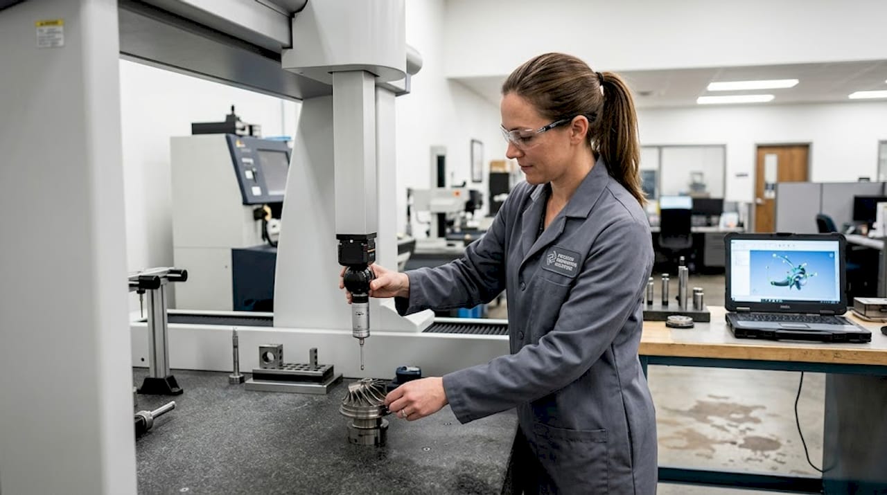
Prototype and environmental testing rounds out the verification picture. Thermal cycling, vibration exposure, and functional fit checks on prototypes reveal how well the tolerance scheme holds up under real operating conditions, not just on the CMM table. Reviewing part quality verification methods gives procurement managers a clear picture of what to require from suppliers.
Pro Tip: Build cross-functional design reviews into your program schedule before drawing release. Bringing quality and manufacturing engineers into the conversation at the design stage, rather than at first article, is the single highest-leverage action for avoiding tolerance-related delays. For deeper insight into how quality and throughput can coexist, the conversation starts with early process capability data.
Our take: Why collaboration and early decisions create tolerance success
After nearly four decades of machining precision components for aerospace and defense programs, we at Machining Technologies have seen a consistent pattern: tolerance problems are almost never a machine problem. They are a communication problem.
The most expensive failures occur when design engineers specify tolerances in isolation, procurement selects suppliers purely on price, and manufacturing gets handed a drawing they had no input on. The GD&T is technically correct. The machines are capable. But the design choices were not grounded in what is actually achievable at production volume.
Real tolerance excellence comes from combining rigorous standards knowledge with hands-on shop-floor experience, and then validating assumptions with data from actual prototypes. The shops that deliver the best outcomes are not just order-takers. They proactively review incoming drawings, flag over-toleranced features, and recommend adjustments before a single chip is cut.
Exploring strategies for complex part manufacturing makes clear that this kind of proactive engagement is not a luxury on aerospace programs. It is the standard that separates programs that ship on time from those that stall at first article.
Partner with experts for flawless tolerance outcomes
Applying these best practices requires more than a checklist. It requires a manufacturing partner who lives them every day across thousands of complex aerospace and defense components.
At Machining Technologies, we have supported aerospace and defense OEMs since 1985 with AS9100D-compliant precision machining across our 70,000 square foot facility in Webster, Massachusetts. From tolerance reviews at the design stage through full-scale production, we bring the process controls and verification systems your program demands. Learn about the contract machining benefits that keep aerospace programs on schedule, or explore our precision manufacturing strategies to see how we approach critical tolerance challenges from first article through high-volume delivery.
Frequently asked questions
What is the standard tolerance range for aerospace machining?
Aerospace tolerances for critical features typically range from ±0.005mm to ±0.010mm, which is significantly tighter than standard CNC machining at ±0.25mm. Feature function and safety classification determine which tier applies.
How does using statistical tolerance analysis save costs?
Statistical analysis predicts real-world manufacturing variation so engineers can apply tight tolerances only where the function demands them, avoiding unnecessary scrap and elevated machining costs on non-critical features.
Why is AS9100D compliance important in tolerance management?
AS9100D compliance mandates full traceability, documented process control, and verified inspection systems, which are all mandatory for producing aerospace parts that can be certified and delivered to program requirements.
What’s the role of advanced fixturing in achieving tight tolerances?
Advanced fixturing holds parts rigidly and repeatably across every cycle, eliminating the distortion and positional variation that cause non-conformances when machining tough aerospace alloys at sub-0.025mm tolerances.
How do I choose which features need the tightest tolerances?
Prioritize features that directly affect fit, form, or safety, and reserve tight tolerances for mating interfaces, bearing surfaces, and aerodynamic geometries. Engage manufacturing and procurement early to validate that your tightest specs are actually achievable at production volume.
Recommended
- Aerospace machining best practices for precision | Machining Technologies
- How to specify machining tolerances for precision | Machining Technologies
- Aerospace machining: precision processes and standards | Machining Technologies
- Why choose custom machining for aerospace and defense | Machining Technologies