

TL;DR:
- Tooling is the true leverage point in aerospace precision manufacturing, profoundly impacting part conformance and process reliability.
- Effective tooling decisions are system-based, involving substrate, coating, geometry, and coolant delivery, which influence accuracy, surface finish, and stability.
Spend enough time in aerospace and defense machining, and you will hear the same assumption repeated with confidence: precision starts with the machine. Buy a better CNC, the thinking goes, and your tolerance problems disappear. That belief is wrong, and acting on it is expensive. Tooling is the real leverage point in high-stakes precision manufacturing, operating as part of a coupled system that shapes dimensional accuracy, surface integrity, thermal behavior, vibration risk, and batch repeatability from the first cut to the last. This article breaks down exactly how tooling decisions translate into mission-critical outcomes for engineers and procurement teams working in aerospace and defense environments.
Table of Contents
- Why tooling is central to aerospace precision
- Technical factors: What makes a tool “precision-ready”?
- Real-world challenges: Beyond the catalog specs
- Tooling selection as system risk management
- Benchmarking and validation: Proving precision before production
- What most engineers miss about tooling and precision
- Advance your precision strategy with specialized machining solutions
- Frequently asked questions
Key Takeaways
| Point | Details |
|---|---|
| Tooling is system-critical | Precision in aerospace and defense manufacturing relies on tooling as part of an integrated process, not as an isolated factor. |
| Validation trumps catalog specs | Production-like testing and benchmarking are essential for proving true precision beyond manufacturer claims. |
| Risk and sustainment matter | Tooling decisions should balance immediate performance with long-term reliability and maintenance impacts. |
| Technical nuance drives results | Small changes in tool material, geometry, and process settings can make substantial differences with difficult alloys. |
Why tooling is central to aerospace precision
Most engineers understand that precision requires tight process control. Fewer appreciate how much of that control lives in the tooling stack. The machine provides the motion platform, but tooling determines how energy transfers into the workpiece, how heat is managed at the cutting zone, and whether that process repeats reliably across 500 parts or 50,000.
In aerospace, tooling affects dimensional accuracy, surface finish, thermal effects, vibration, and repeatability simultaneously. Change one element of the tooling setup and you shift all of them. That interdependency is what makes tooling decisions genuinely difficult and genuinely important.
Think of the system this way. Tool, holder, workholding, coolant delivery, machine spindle, and process control software are all nodes in a single network. A premium carbide end mill running in a worn collet holder with inadequate coolant pressure will underperform a mid-range tool in a properly balanced hydraulic holder with through-spindle coolant. The catalog spec tells you what the tool can do. Your actual setup determines what it will do.
Key system factors that interact with every tooling choice:
- Runout at the tool tip: Even 0.0002 inches of runout at the holder can translate into measurable surface finish degradation and asymmetric tool wear
- Chatter and harmonic response: Tool overhang, diameter, and flute geometry each influence the system’s tendency to vibrate at frequencies that leave surface waviness on critical features
- Heat accumulation at the interface: Poorly matched coolant delivery raises cutting zone temperatures, alters material microstructure, and introduces thermal growth in the part itself
- Datum transfer reliability: Every workholding change introduces the potential for positional shift; tooling must compensate for or minimize those shifts
Understanding aerospace machining tolerances at the system level, rather than the individual tool level, is what separates teams that hit their numbers consistently from those that sort and rework at the end of every run.
Tooling is not a consumable line item in aerospace production. It is a process variable with direct influence on part conformance, and it deserves the same engineering rigor applied to any other controlled variable in your quality plan.
The most reliable teams we work with treat tooling selection as an engineering decision, not a purchasing transaction. They document tool performance against precision process standards and feed that data back into future setups. That feedback loop is where real process capability is built.
Technical factors: What makes a tool “precision-ready”?
Four variables dominate tooling performance in high-precision aerospace and defense work: substrate, coating, geometry, and coolant delivery. Getting all four right for a specific material and feature type is not trivial, but the trade-off logic is learnable.
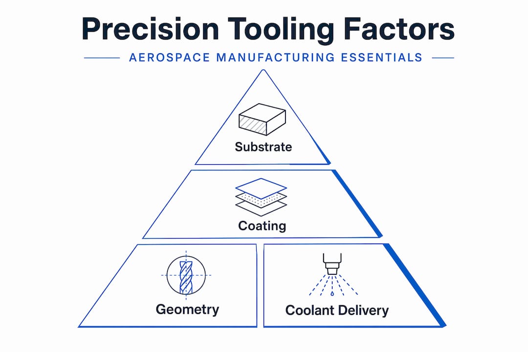
Substrate refers to the base material of the cutting tool, most commonly carbide grades ranging from fine to ultrafine grain. Ultrafine grain carbide supports sharper edge preparation and holds that edge more consistently under intermittent cut conditions, which matters enormously in titanium and nickel alloy components where work hardening is a real risk.
Coatings modify the tool’s thermal and tribological behavior at the cutting interface. TiAlN (Titanium Aluminum Nitride) coatings, for example, form a protective aluminum oxide layer at elevated temperatures, making them well suited for dry or near-dry machining of hardened steels and superalloys. AlTiN variants push that temperature ceiling higher. The wrong coating in the wrong application accelerates wear and introduces dimensional drift mid-batch.
Geometry controls how the tool engages the material. Positive rake angles reduce cutting forces and are favored in softer alloys, while negative or neutral rake geometries provide edge strength for interrupted cuts in harder materials. Helix angle affects chip evacuation and axial cutting forces. Corner radius affects surface finish and edge strength. Each choice is a trade-off, and that trade-off shifts when you move from roughing to finishing or from aluminum to Inconel.
Coolant delivery is frequently underspecified. Advanced tooling choices, including coatings, geometry, and coolant strategy, dramatically affect tool life and process stability with difficult materials like Inconel 718. Through-spindle coolant at adequate pressure (often 70 bar or higher) changes the thermal equation completely compared to flood coolant from an external nozzle. For deep features or small-diameter tools, minimum quantity lubrication (MQL) can outperform flood coolant by keeping chips mobile and temperatures stable.
| Tool setup | Material suitability | Tool life estimate | Surface finish risk | Cost tier |
|---|---|---|---|---|
| Uncoated carbide, standard geometry | Aluminum, soft steel | Moderate | Low | Low |
| TiAlN coated, positive rake | Ti-6Al-4V, hardened steel | High | Low to moderate | Medium |
| AlTiN coated, neutral rake, MQL | Inconel 718, superalloys | Very high | Moderate | High |
| PCD tipped, high helix | Aluminum, CFRP composites | Very high | Very low | Premium |
Pro Tip: When qualifying a new tool for an Inconel or titanium feature, run a short tool-life test at three speed-feed combinations before committing to a production parameter set. The sweet spot for tool life is rarely where the catalog suggests, and finding it with 20 parts saves you from discovering it with 2,000.
Aligning your tool selection to documented precision best practices and maintaining validated tolerance strategies across your tooling library gives procurement teams a defensible baseline when qualifying new suppliers or new part families.
Real-world challenges: Beyond the catalog specs
Catalog data describes what a tool can achieve under controlled laboratory conditions. Production environments are rarely laboratory conditions. The gap between spec-sheet precision and actual achievable precision is where most field problems live.
Precision erodes when process instability increases. Deflection, fixture compliance, thermal growth, and measurement uncertainty can consume much of the tolerance budget before a single cut is made. On a part with a 0.001-inch bilateral tolerance, a fixturing compliance of 0.0004 inches, a thermal growth of 0.0003 inches, and a CMM measurement uncertainty of 0.0002 inches together account for 0.0009 inches of the budget. The actual cutting process has almost nothing left to spend.
| Error source | Typical contribution | Mitigation strategy |
|---|---|---|
| Fixture compliance | 0.0002 to 0.0005 in | Rigid, repeatable workholding; reduced clamping force variation |
| Tool deflection | 0.0001 to 0.0004 in | Shorter overhang, larger diameter tools, reduced depth of cut |
| Thermal growth (spindle/part) | 0.0001 to 0.0003 in | Warm-up cycles, temperature-controlled environment |
| Datum transfer error | 0.0001 to 0.0003 in | Minimized setups, precision locating features |
| CMM measurement uncertainty | 0.0001 to 0.0002 in | Calibrated probes, controlled measurement environment |
Thin-walled aerospace features expose all of these stack-ups simultaneously. A titanium housing with 0.040-inch walls deflects under cutting force, moves with temperature, and then springs back when unclamped. The tooling strategy for that part must address cutting force magnitude (through geometry and feeds), heat input (through coolant and speeds), and sequencing (rough, stress relieve, then finish) as an integrated plan, not as individual line items.
Test-piece benchmarking provides a structured way to expose these stack-ups before production begins. Rather than guessing at tolerances from a catalog, you cut a standardized test geometry that exercises the same features (pockets, bores, surfaces, angled faces) your production part requires, then measure the results with CMM. The deviation map tells you exactly where your process budget is going and whether your tooling configuration is adequate.
This is directly relevant to high-volume workflow optimization. Catching a fixturing compliance problem at the test-piece stage costs hours. Catching it after 10,000 production parts costs a program. Similarly, tooling choices that perform acceptably in multi-axis machining on a simple prismatic part may fail when the same machine tilts the table to reach compound angles, changing the dynamic load on every tool in the carousel.
Tooling selection as system risk management
Procurement teams in defense programs often face a difficult tension: new tooling technologies promise better performance, but “better” has to mean better across the whole operational picture, not just on a test coupon.

Cutting-edge capability is not sufficient if maintainability and sustainment are weak. A tooling strategy that demands specialized regrind services, proprietary holders, or long lead-time insert grades creates operational risk in defense production environments where schedule reliability matters as much as dimensional accuracy.
Before committing to a tooling strategy for a long-run defense component, procurement and engineering should work through these questions together:
- What is the tool change frequency under expected production volumes? Frequent changes increase downtime and introduce setup variation.
- Is the tooling available through multiple qualified distributors? Single-source tooling creates supply chain risk on programs with long production runs.
- What does regrind or reconditioning cost, and who performs it? In-house regrind capability may be more economical and controllable than outsourced services.
- How does the tooling perform across the full range of production materials, not just the nominal alloy? Material variations between heats can shift optimal cutting parameters significantly.
- What are the inspection and monitoring requirements? Some high-performance tooling requires in-process force monitoring or tool-life counters that add system complexity.
- Does the tooling support your quality documentation requirements? Traceability from tool batch to part serial number is increasingly standard in defense contracts.
The most dangerous tooling decision in defense manufacturing is choosing based on best-case performance data without stress-testing the sustainment model. A tool that cuts beautifully but cannot be sourced on short notice is a liability, not an asset.
Framing tooling selection as risk management rather than specification matching changes the conversation entirely. Engineers and buyers working on defense precision programs who integrate sustainment thinking into their tooling decisions consistently outperform teams that optimize for cut time alone. Custom aerospace machining strategies built around verified, sustainable tooling are more predictable and far easier to scale.
Benchmarking and validation: Proving precision before production
The transition from a qualified tool to a validated process requires systematic benchmarking. Engineering teams that skip this step are essentially betting production conformance on untested assumptions.
Test-piece methodologies translate real component critical features into measurable test geometries, then benchmark system accuracy under actual dynamic loads. This is not a simulation. The test piece is cut on the actual machine, with the actual tooling, holders, coolant system, and operator setup. CMM inspection then reveals where the system performs and where it does not.
A rigorous test-piece validation process for tooling qualification should cover:
- Feature selection: Include geometries representative of production-critical features (e.g., bores, slots, angled surfaces, thin walls, deep pockets)
- Condition matching: Run the test at production spindle speeds, feeds, and depths of cut, not conservative test parameters
- Thermal cycling: Allow the machine and tooling to reach thermal equilibrium before measuring, then repeat measurements after a controlled interruption to capture thermal drift behavior
- Positional repeatability: Run the same test piece multiple times across different shifts or operators to assess setup repeatability, not just machine accuracy
- CMM correlation: Use a traceable CMM with measurement uncertainty documented and accounted for in the acceptance criteria
- Deviation mapping: Plot CMM results against nominal geometry to identify systematic errors (common with worn holders or thermal drift) versus random errors (common with fixturing or vibration)
The output of this process is a documented capability statement for the tooling and process combination, not just for the tool in isolation. That distinction matters enormously when you are presenting conformance evidence to a customer or qualifying a process with a regulatory body.
Staying current with machining trends in 2026 means recognizing that tooling validation is evolving. In-process measurement, force monitoring, and adaptive control are increasingly available at affordable system cost, and they can compress validation timelines significantly by catching deviation in real time rather than at final inspection.
What most engineers miss about tooling and precision
After decades of machining aerospace and defense components, the pattern we see most often is this: engineering teams invest heavily in machine technology and then underinvest in the process rigor that determines whether that machine delivers on its potential. The tool catalog replaces the engineering analysis. Cost-per-edge replaces cost-per-conformant-part. And when the process underperforms, the first instinct is to look at the machine, not the system.
The uncomfortable truth is that repeatable precision in aerospace and defense work depends less on having the most advanced tools and more on controlling every process variable upstream of the cut. That means documented setups, validated workholding, characterized tooling, and a benchmarked measurement system. A modest tool in a tightly controlled system outperforms a premium tool in an uncontrolled one, every time.
Procurement professionals have a specific role to play here. Demanding tool cost comparisons without also demanding documented test-piece results and total cost of system operation is a false economy. The best practices overview we advocate for is simple: no tooling strategy should be accepted without evidence of performance under production-equivalent conditions. Catalog data is a starting point, not a qualification.
The teams that get this right do not just build better parts. They build predictable processes, and predictable processes scale. When you scale, you win programs.
Advance your precision strategy with specialized machining solutions
If the tooling and process framework described in this article aligns with the precision challenges you are working through, Machining Technologies LLC can translate that framework into verified production outcomes. Since 1985, our 70,000 square foot facility in Webster, Massachusetts has produced over 20 million parts annually for aerospace, defense, and industrial clients who demand conformance at every scale.
Our team brings deep expertise in contract machining for high-volume and prototype runs, with advanced CNC milling, turning, Hydromat systems, and precision manufacturing strategies designed for complex, tight-tolerance components. For features that require the highest accuracy regardless of geometry, our wire EDM capabilities deliver where conventional cutting reaches its limits. Contact our engineering team to discuss your precision requirements and build a tooling and process strategy backed by real production data.
Frequently asked questions
How can I validate that a tooling solution will achieve required precision?
Use production-equivalent test-piece methods and CMM inspection to benchmark tooling performance against real component features rather than relying on catalog specifications.
What factors besides tool geometry most limit achievable precision?
Deflection, fixturing compliance, thermal growth, and measurement uncertainty are major contributors to tolerance stack-up and often consume most of the tolerance budget before cutting begins.
Do high-performance tools always reduce production costs?
Not necessarily. If tool change frequency or sustainment burden rises, total costs including downtime, regrind, and maintenance can increase even if per-edge cost drops.
Is there a standard for assessing multi-axis precision in aerospace machining?
Industry test-piece methodologies with CMM-measured results are the accepted standard for benchmarking multi-axis system accuracy under real dynamic production loads.
Recommended
- Machining in defense industry: precision and innovation | Machining Technologies
- Why choose custom machining for aerospace and defense | Machining Technologies
- Best practices in tolerances for aerospace precision machining | Machining Technologies
- Why tight tolerances matter for aerospace machining | Machining Technologies